com.io7m.jcamera
0.6.0
com.io7m.jcamera 0.6.0 Documentation
Package Information
Orientation
Installation
Source compilation
$ mvn -C clean install
Maven
Regular releases are made to the
Central Repository,
so it's possible to use the
com.io7m.jcamera
package in your projects with the following Maven dependency:
<dependency>
  <groupId>com.io7m.jcamera</groupId>
  <artifactId>com.io7m.jcamera-core</artifactId>
  <version>0.6.0</version>
</dependency>
License
All files distributed with the
com.io7m.jcamera
package are placed under the following license:
Copyright © 2021 Mark Raynsford <code@io7m.com> https://www.io7m.com

Permission to use, copy, modify, and/or distribute this software for any
purpose with or without fee is hereby granted, provided that the above
copyright notice and this permission notice appear in all copies.

THE SOFTWARE IS PROVIDED "AS IS" AND THE AUTHOR DISCLAIMS ALL WARRANTIES
WITH REGARD TO THIS SOFTWARE INCLUDING ALL IMPLIED WARRANTIES OF
MERCHANTABILITY AND FITNESS. IN NO EVENT SHALL THE AUTHOR BE LIABLE FOR
ANY SPECIAL, DIRECT, INDIRECT, OR CONSEQUENTIAL DAMAGES OR ANY DAMAGES
WHATSOEVER RESULTING FROM LOSS OF USE, DATA OR PROFITS, WHETHER IN AN
ACTION OF CONTRACT, NEGLIGENCE OR OTHER TORTIOUS ACTION, ARISING OUT OF
OR IN CONNECTION WITH THE USE OR PERFORMANCE OF THIS SOFTWARE.
Usage
Usage
Overview
This section attempts to describe how to use the
com.io7m.jcamera
package. The
example code uses
JOGL
but the package can obviously be used under any Java input/windowing
system.
This section doesn't attempt to explain why anything works the way it does
-
readers are encouraged to read the
design and implementation
section, which
describes everything in extensive detail.
A complete listing of all example source files is available
at the end of the section.
First-person camera
Overview
In order to aid comprehension, and to follow good software engineering
practices, the usage example here will be developed as a set of types
with well-defined interfaces. Specifically, a simple main program will
initialize an OpenGL window with JOGL, and register some keyboard and
mouse listeners to supply input to a
simulation, which in turn periodically
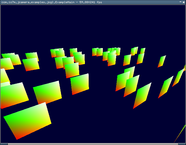
produces new data (a view matrix) for
a renderer.
The renderer draws a simple static scene
using the view matrix periodically produced by a camera from the
com.io7m.jcamera
package. The
simulation
runs at a fixed time step
to provide completely frame rate independent movement (see the article
"Fix Your Timestep!"
for details on why physical simulations should use fixed time steps).
The renderer, however, runs at an arbitrary
frame rate. On some systems the frame rate will be exactly equal to the
screen's vertical refresh rate, whilst on others, the rate will be
thousands of times per second. The desire is to show that the system
works equally well no matter what frame rate is used, so no attempt
is made to enforce any particular rate. A rough graph of the data
flow between components is as follows:
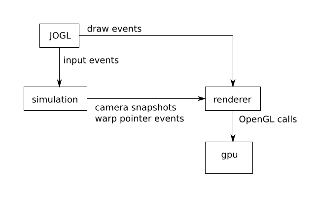
JOGL works with an event-based model, where mouse and keyboard input
causes events to be delivered to mouse and keyboard
listeners.
Additionally, OpenGL rendering typically occurs via an OpenGL
listener: JOGL (or the GPU, or the
operating system,
whichever is responsible) indicates that it is time to render the scene,
and the user's registered listener is
executed to actually perform the drawing. It's reasonable to assume that
input handling and rendering occur on different threads by default, so
the code here is careful to operate in a thread-safe manner.
The interface exposed to JOGL by the example renderer is as follows
[
ExampleRendererType.java]:
        /*
 * Copyright © 2021 Mark Raynsford <code@io7m.com> https://www.io7m.com
 *
 * Permission to use, copy, modify, and/or distribute this software for any
 * purpose with or without fee is hereby granted, provided that the above
 * copyright notice and this permission notice appear in all copies.
 *
 * THE SOFTWARE IS PROVIDED "AS IS" AND THE AUTHOR DISCLAIMS ALL WARRANTIES
 * WITH REGARD TO THIS SOFTWARE INCLUDING ALL IMPLIED WARRANTIES OF
 * MERCHANTABILITY AND FITNESS. IN NO EVENT SHALL THE AUTHOR BE LIABLE FOR ANY
 * SPECIAL, DIRECT, INDIRECT, OR CONSEQUENTIAL DAMAGES OR ANY DAMAGES
 * WHATSOEVER RESULTING FROM LOSS OF USE, DATA OR PROFITS, WHETHER IN AN
 * ACTION OF CONTRACT, NEGLIGENCE OR OTHER TORTIOUS ACTION, ARISING OUT OF OR
 * IN CONNECTION WITH THE USE OR PERFORMANCE OF THIS SOFTWARE.
 */

package com.io7m.jcamera.examples.jogl;

import com.io7m.jcamera.JCameraReadableSnapshotType;
import com.io7m.jtensors.core.unparameterized.vectors.Vector3D;
import com.jogamp.newt.opengl.GLWindow;
import com.jogamp.opengl.GL3;

import java.io.IOException;
import java.util.Optional;

/**
 * The interface exposed by the renderer to JOGL.
 */

public interface ExampleRendererType extends ExampleRendererControllerType
{
  /**
   * Initialize the scene, using the given window and OpenGL interface.
   *
   * @param in_window The window
   * @param in_gl     The OpenGL interface
   *
   * @throws IOException On I/O errors
   */

  void init(
    GLWindow in_window,
    GL3 in_gl)
    throws IOException;

  /**
   * Draw the scene.
   *
   * @param s      A camera snapshot
   * @param target An optional target to be drawn
   */

  void draw(
    JCameraReadableSnapshotType s,
    Optional<Vector3D> target);

  /**
   * Indicate that the screen has been resized.
   *
   * @param width  The new width
   * @param height The new height
   */

  void reshape(
    int width,
    int height);
}
Little is needed in the way of explanation here. The renderer initializes
the scene's resources when init is
called (such as allocating memory on the GPU for mesh data, compiling
shaders, etc).
The renderer draws the scene whenever draw
is called,
and recalculates any internal resources that are dependent on the size
of the window (such as the scene's projection
matrix)
when reshape is called.
The actual implementation of the renderer is of little interest here. It
simply draws a hundred or so static quads from the perspective of whatever
is the current view matrix. The implementation is given in
ExampleRenderer
and will not be referenced again.
FPS Simulation
The interface exposed to JOGL by the example simulation is as follows
[
ExampleFPSStyleSimulationType.java]:
        /*
 * Copyright © 2021 Mark Raynsford <code@io7m.com> https://www.io7m.com
 *
 * Permission to use, copy, modify, and/or distribute this software for any
 * purpose with or without fee is hereby granted, provided that the above
 * copyright notice and this permission notice appear in all copies.
 *
 * THE SOFTWARE IS PROVIDED "AS IS" AND THE AUTHOR DISCLAIMS ALL WARRANTIES
 * WITH REGARD TO THIS SOFTWARE INCLUDING ALL IMPLIED WARRANTIES OF
 * MERCHANTABILITY AND FITNESS. IN NO EVENT SHALL THE AUTHOR BE LIABLE FOR ANY
 * SPECIAL, DIRECT, INDIRECT, OR CONSEQUENTIAL DAMAGES OR ANY DAMAGES
 * WHATSOEVER RESULTING FROM LOSS OF USE, DATA OR PROFITS, WHETHER IN AN
 * ACTION OF CONTRACT, NEGLIGENCE OR OTHER TORTIOUS ACTION, ARISING OUT OF OR
 * IN CONNECTION WITH THE USE OR PERFORMANCE OF THIS SOFTWARE.
 */

package com.io7m.jcamera.examples.jogl;

import com.io7m.jcamera.JCameraFPSStyleInputType;
import com.io7m.jcamera.JCameraFPSStyleIntegratorType;
import com.io7m.jcamera.JCameraFPSStyleSnapshot;
import com.io7m.jcamera.JCameraFPSStyleType;

/**
 * The interface to simulations (with fps-style cameras) exposed to JOGL.
 */

public interface ExampleFPSStyleSimulationType
{
  /**
   * @return {@code true} if the camera is enabled.
   */

  boolean cameraIsEnabled();

  /**
   * Enable/disable the camera.
   *
   * @param b {@code true} if the camera should be enabled.
   */

  void cameraSetEnabled(
    boolean b);

  /**
   * @return The camera used for the simulation.
   */

  JCameraFPSStyleType getCamera();

  /**
   * @return The simulation delta time
   */

  float getDeltaTime();

  /**
   * @return The camera input
   */

  JCameraFPSStyleInputType getInput();

  /**
   * @return The integrator used for the camera.
   */

  JCameraFPSStyleIntegratorType getIntegrator();

  /**
   * @return A new camera snapshot
   */

  JCameraFPSStyleSnapshot integrate();
}
Again, little is needed in the way of explanation. The simulation provides
a
camera that can be enabled and disabled. If the camera is disabled,
a simple fixed camera is used rather than having the camera be driven by
keyboard and mouse input.
The simulation needs a way to periodically warp the mouse cursor to the
center of the screen if the movable camera is enabled, so the renderer
exposes the following interface to the simulation
[
ExampleRendererControllerType.java]:
        /*
 * Copyright © 2021 Mark Raynsford <code@io7m.com> https://www.io7m.com
 *
 * Permission to use, copy, modify, and/or distribute this software for any
 * purpose with or without fee is hereby granted, provided that the above
 * copyright notice and this permission notice appear in all copies.
 *
 * THE SOFTWARE IS PROVIDED "AS IS" AND THE AUTHOR DISCLAIMS ALL WARRANTIES
 * WITH REGARD TO THIS SOFTWARE INCLUDING ALL IMPLIED WARRANTIES OF
 * MERCHANTABILITY AND FITNESS. IN NO EVENT SHALL THE AUTHOR BE LIABLE FOR ANY
 * SPECIAL, DIRECT, INDIRECT, OR CONSEQUENTIAL DAMAGES OR ANY DAMAGES
 * WHATSOEVER RESULTING FROM LOSS OF USE, DATA OR PROFITS, WHETHER IN AN
 * ACTION OF CONTRACT, NEGLIGENCE OR OTHER TORTIOUS ACTION, ARISING OUT OF OR
 * IN CONNECTION WITH THE USE OR PERFORMANCE OF THIS SOFTWARE.
 */

package com.io7m.jcamera.examples.jogl;

/**
 * The interface that the simulation uses to talk to the renderer.
 */

public interface ExampleRendererControllerType
{
  /**
   * Tell the renderer/windowing system that it should warp the pointer to the
   * center of the screen.
   */

  void sendWantWarpPointer();
}
The actual implementation of the simulation is as follows
[
ExampleFPSStyleSimulation.java].
First:
          /**
   * $example: Construct a new simulation.
   *
   * @param in_renderer The interface to the renderer
   */

  public ExampleFPSStyleSimulation(
    final ExampleRendererControllerType in_renderer)
  {
    this.renderer = in_renderer;
    this.input = JCameraFPSStyleInput.newInput();
    this.camera = JCameraFPSStyle.newCamera();
    final JCameraFPSStyleType camera_fixed = JCameraFPSStyle.newCamera();
    this.fixed_snapshot = JCameraFPSStyleSnapshots.of(camera_fixed);
    this.camera_enabled = new AtomicBoolean(false);
Then, an integrator is
created to drive the camera, and the integration
period required for a fixed time step of
60
frames per second is calculated:
            /*
     * $example: Construct an integrator using the default implementations.
     */

    this.integrator =
      JCameraFPSStyleIntegrator.newIntegrator(this.camera, this.input);

    /*
     * Work out what fraction of a second the given simulation rate is going
     * to require.
     */

    final float rate = 60.0f;
    this.integrator_time_seconds = 1.0f / rate;
Finally, to give the camera somewhat more snappy and abrupt behaviour than
the default settings, some new acceleration and drag values are configured
for the camera:
            /*
     * $example: Configure the integrator. Use a high drag factor to give
     * quite abrupt stops, and use high rotational acceleration.
     */

    this.integrator.integratorAngularSetDragHorizontal(0.000000001);
    this.integrator.integratorAngularSetDragVertical(0.000000001);
    this.integrator.integratorAngularSetAccelerationHorizontal(
      Math.PI / 12.0 / (double) this.integrator_time_seconds);
    this.integrator.integratorAngularSetAccelerationVertical(
      Math.PI / 12.0 / (double) this.integrator_time_seconds);
    this.integrator.integratorLinearSetAcceleration(
      3.0 / (double) this.integrator_time_seconds);
    this.integrator.integratorLinearSetMaximumSpeed(3.0);
    this.integrator.integratorLinearSetDrag(0.000000001);
  }
The integrate function is executed at a
rate of 60 times per second, and
produces a new snapshot each time, which is passed to the renderer.
The immutable nature of the snapshot means that it can be safely shared
across threads without any need for locks or other synchronization.
If the camera is actually enabled, the simulation also instructs the
renderer to warp the mouse cursor back to the center of the screen. The
rest of the functions complete the interface.
          /**
   * $example: Integrate the camera.
   *
   * @return A new camera snapshot.
   */

  @Override
  public JCameraFPSStyleSnapshot integrate()
  {
    /*
     * If the camera is actually enabled, integrate and produce a snapshot,
     * and then tell the renderer/window system that it should warp the
     * pointer back to the center of the screen.
     */

    if (this.cameraIsEnabled()) {
      this.integrator.integrate(this.integrator_time_seconds);
      final JCameraFPSStyleSnapshot snap =
        JCameraFPSStyleSnapshots.of(this.camera);
      this.renderer.sendWantWarpPointer();
      return snap;
    }

    return this.fixed_snapshot;
  }

  @Override
  public boolean cameraIsEnabled()
  {
    return this.camera_enabled.get();
  }

  @Override
  public void cameraSetEnabled(
    final boolean b)
  {
    this.camera_enabled.set(b);
  }

  @Override
  public float getDeltaTime()
  {
    return this.integrator_time_seconds;
  }

  @Override
  public JCameraFPSStyleInputType getInput()
  {
    return this.input;
  }

  @Override
  public JCameraFPSStyleIntegratorType getIntegrator()
  {
    return this.integrator;
  }

  @Override
  public JCameraFPSStyleType getCamera()
  {
    return this.camera;
  }
}
Input
It's now necessary to supply the simulation with input.
A KeyListener is defined.
Every time the user presses or releases a key, the simulation camera's
input is notified accordingly.
There is one main issue covered here: If the user has keyboard
auto-repeat enabled by their operating system, holding a key will result
in
an endless stream of "key pressed" and "key released" events. The code
here
is only interested in receiving the first "key pressed" and last "key
released"
event for each key, and JOGL's NEWT system marks each event as having been
produced by auto-repeat (or not). Therefore, the auto-repeat flag is
checked
for each event, and the event is discarded if the flag is set.
Additionally, a few extra definitions allow for showing/hiding the mouse
cursor, and switching between windowed and full-screen mode. JOGL requires
that the setFullscreen function be
called
on a background thread, rather than the thread handling input and/or
rendering for the current window.
        /*
 * Copyright © 2021 Mark Raynsford <code@io7m.com> https://www.io7m.com
 *
 * Permission to use, copy, modify, and/or distribute this software for any
 * purpose with or without fee is hereby granted, provided that the above
 * copyright notice and this permission notice appear in all copies.
 *
 * THE SOFTWARE IS PROVIDED "AS IS" AND THE AUTHOR DISCLAIMS ALL WARRANTIES
 * WITH REGARD TO THIS SOFTWARE INCLUDING ALL IMPLIED WARRANTIES OF
 * MERCHANTABILITY AND FITNESS. IN NO EVENT SHALL THE AUTHOR BE LIABLE FOR ANY
 * SPECIAL, DIRECT, INDIRECT, OR CONSEQUENTIAL DAMAGES OR ANY DAMAGES
 * WHATSOEVER RESULTING FROM LOSS OF USE, DATA OR PROFITS, WHETHER IN AN
 * ACTION OF CONTRACT, NEGLIGENCE OR OTHER TORTIOUS ACTION, ARISING OUT OF OR
 * IN CONNECTION WITH THE USE OR PERFORMANCE OF THIS SOFTWARE.
 */

package com.io7m.jcamera.examples.jogl;

import com.io7m.jcamera.JCameraFPSStyleInputType;
import com.jogamp.newt.event.InputEvent;
import com.jogamp.newt.event.KeyEvent;
import com.jogamp.newt.event.KeyListener;
import com.jogamp.newt.opengl.GLWindow;

import java.util.concurrent.ExecutorService;

/**
 * The key listener used to handle keyboard events.
 */

// CHECKSTYLE_JAVADOC:OFF

@SuppressWarnings("synthetic-access")
public final class ExampleFPSStyleKeyListener implements
  KeyListener
{
  private final ExampleFPSStyleSimulationType sim;
  private final ExecutorService background_workers;
  private final ExampleRendererType renderer;
  private final JCameraFPSStyleInputType input;
  private final GLWindow window;

  public ExampleFPSStyleKeyListener(
    final ExampleFPSStyleSimulationType in_sim,
    final ExecutorService in_background_workers,
    final ExampleRendererType in_renderer,
    final GLWindow in_window)
  {
    this.sim = in_sim;
    this.background_workers = in_background_workers;
    this.renderer = in_renderer;
    this.input = in_sim.getInput();
    this.window = in_window;
  }

  @Override
  public void keyPressed(
    final KeyEvent e)
  {
    assert e != null;

    /*
     * Ignore events that are the result of keyboard auto-repeat. This means
     * there's one single event when a key is pressed, and another when it is
     * released (as opposed to an endless stream of both when the key is held
     * down).
     */

    if ((e.getModifiers() & InputEvent.AUTOREPEAT_MASK) == InputEvent.AUTOREPEAT_MASK) {
      return;
    }

    switch (e.getKeyCode()) {

      /*
       * Standard WASD camera controls, with E and Q moving up and down,
       * respectively.
       */

      case KeyEvent.VK_A: {
        this.input.setMovingLeft(true);
        break;
      }
      case KeyEvent.VK_W: {
        this.input.setMovingForward(true);
        break;
      }
      case KeyEvent.VK_S: {
        this.input.setMovingBackward(true);
        break;
      }
      case KeyEvent.VK_D: {
        this.input.setMovingRight(true);
        break;
      }
      case KeyEvent.VK_E: {
        this.input.setMovingUp(true);
        break;
      }
      case KeyEvent.VK_Q: {
        this.input.setMovingDown(true);
        break;
      }
    }
  }

  @Override
  public void keyReleased(
    final KeyEvent e)
  {
    assert e != null;

    /*
     * Ignore events that are the result of keyboard auto-repeat. This means
     * there's one single event when a key is pressed, and another when it is
     * released (as opposed to an endless stream of both when the key is held
     * down).
     */

    if ((e.getModifiers() & InputEvent.AUTOREPEAT_MASK) == InputEvent.AUTOREPEAT_MASK) {
      return;
    }

    switch (e.getKeyCode()) {

      /*
       * Pressing 'M' enables/disables the camera.
       */

      case KeyEvent.VK_M: {
        this.toggleCameraEnabled();
        break;
      }

      /*
       * Pressing 'P' makes the mouse cursor visible/invisible.
       */

      case KeyEvent.VK_P: {
        System.out.printf(
          "Making pointer %s\n",
          this.window.isPointerVisible() ? "invisible" : "visible");
        this.window.setPointerVisible(!this.window.isPointerVisible());
        break;
      }

      /*
       * Pressing enter switches between windowed and fullscreen mode. JOGL
       * requires that this be executed on a background thread.
       */

      case KeyEvent.VK_ENTER: {
        this.background_workers.execute(new Runnable()
        {
          @Override
          public void run()
          {
            final boolean mode =
              !ExampleFPSStyleKeyListener.this.window.isFullscreen();
            ExampleFPSStyleKeyListener.this.window.setFullscreen(mode);
          }
        });
        break;
      }

      /*
       * Standard WASD camera controls, with E and Q moving up and down,
       * respectively.
       */

      case KeyEvent.VK_A: {
        this.input.setMovingLeft(false);
        break;
      }
      case KeyEvent.VK_W: {
        this.input.setMovingForward(false);
        break;
      }
      case KeyEvent.VK_S: {
        this.input.setMovingBackward(false);
        break;
      }
      case KeyEvent.VK_D: {
        this.input.setMovingRight(false);
        break;
      }
      case KeyEvent.VK_E: {
        this.input.setMovingUp(false);
        break;
      }
      case KeyEvent.VK_Q: {
        this.input.setMovingDown(false);
        break;
      }
    }
  }

  public void toggleCameraEnabled()
  {
    final boolean enabled = this.sim.cameraIsEnabled();

    if (enabled) {
      System.out.println("Disabling camera");
      this.window.confinePointer(false);
    } else {
      System.out.println("Enabling camera");
      this.window.confinePointer(true);
      this.renderer.sendWantWarpPointer();
      this.input.setRotationHorizontal(0.0);
      this.input.setRotationVertical(0.0);
    }

    this.sim.cameraSetEnabled(!enabled);
  }
}
A MouseAdapter is defined.
Every time the user moves the mouse, the rotation coefficients are
calculated
and sent to the simulation camera's input:
        /*
 * Copyright © 2021 Mark Raynsford <code@io7m.com> https://www.io7m.com
 *
 * Permission to use, copy, modify, and/or distribute this software for any
 * purpose with or without fee is hereby granted, provided that the above
 * copyright notice and this permission notice appear in all copies.
 *
 * THE SOFTWARE IS PROVIDED "AS IS" AND THE AUTHOR DISCLAIMS ALL WARRANTIES
 * WITH REGARD TO THIS SOFTWARE INCLUDING ALL IMPLIED WARRANTIES OF
 * MERCHANTABILITY AND FITNESS. IN NO EVENT SHALL THE AUTHOR BE LIABLE FOR ANY
 * SPECIAL, DIRECT, INDIRECT, OR CONSEQUENTIAL DAMAGES OR ANY DAMAGES
 * WHATSOEVER RESULTING FROM LOSS OF USE, DATA OR PROFITS, WHETHER IN AN
 * ACTION OF CONTRACT, NEGLIGENCE OR OTHER TORTIOUS ACTION, ARISING OUT OF OR
 * IN CONNECTION WITH THE USE OR PERFORMANCE OF THIS SOFTWARE.
 */

package com.io7m.jcamera.examples.jogl;

import com.io7m.jcamera.JCameraFPSStyleInputType;
import com.io7m.jcamera.JCameraFPSStyleMouseRegion;
import com.io7m.jcamera.JCameraRotationCoefficientsMutable;
import com.jogamp.newt.event.MouseAdapter;
import com.jogamp.newt.event.MouseEvent;

import java.util.concurrent.atomic.AtomicReference;

/**
 * The mouse adapter used to handle mouse events.
 */

// CHECKSTYLE_JAVADOC:OFF

public final class ExampleFPSStyleMouseAdapter extends MouseAdapter
{
  private final AtomicReference<JCameraFPSStyleMouseRegion> mouse_region;
  private final JCameraFPSStyleInputType input;
  private final ExampleFPSStyleSimulationType sim;
  private final JCameraRotationCoefficientsMutable rotations;

  public ExampleFPSStyleMouseAdapter(
    final AtomicReference<JCameraFPSStyleMouseRegion> in_mouse_region,
    final ExampleFPSStyleSimulationType in_sim,
    final JCameraRotationCoefficientsMutable in_rotations)
  {
    this.mouse_region = in_mouse_region;
    this.input = in_sim.getInput();
    this.sim = in_sim;
    this.rotations = in_rotations;
  }

  @Override
  public void mouseMoved(
    final MouseEvent e)
  {
    assert e != null;

    /*
     * If the camera is enabled, get the rotation coefficients for the mouse
     * movement.
     */

    if (this.sim.cameraIsEnabled()) {
      this.rotations.from(
        this.mouse_region.get().coefficients(
          e.getX(),
          e.getY()));
      this.input.addRotationAroundHorizontal(this.rotations.horizontal());
      this.input.addRotationAroundVertical(this.rotations.vertical());
    }
  }
}
Rendering/Interpolation
A GLEventListener is added to the window.
The listener will tell the renderer to draw the scene every time the
OpenGL implementation requires a new frame.
The display method linearly
interpolates
between the most recently received camera snapshots in order to provide
smooth
animation independent of the simulation and/or frame rate.
        /*
 * Copyright © 2021 Mark Raynsford <code@io7m.com> https://www.io7m.com
 *
 * Permission to use, copy, modify, and/or distribute this software for any
 * purpose with or without fee is hereby granted, provided that the above
 * copyright notice and this permission notice appear in all copies.
 *
 * THE SOFTWARE IS PROVIDED "AS IS" AND THE AUTHOR DISCLAIMS ALL WARRANTIES
 * WITH REGARD TO THIS SOFTWARE INCLUDING ALL IMPLIED WARRANTIES OF
 * MERCHANTABILITY AND FITNESS. IN NO EVENT SHALL THE AUTHOR BE LIABLE FOR ANY
 * SPECIAL, DIRECT, INDIRECT, OR CONSEQUENTIAL DAMAGES OR ANY DAMAGES
 * WHATSOEVER RESULTING FROM LOSS OF USE, DATA OR PROFITS, WHETHER IN AN
 * ACTION OF CONTRACT, NEGLIGENCE OR OTHER TORTIOUS ACTION, ARISING OUT OF OR
 * IN CONNECTION WITH THE USE OR PERFORMANCE OF THIS SOFTWARE.
 */

package com.io7m.jcamera.examples.jogl;

import com.io7m.jcamera.JCameraFPSStyleMouseRegion;
import com.io7m.jcamera.JCameraFPSStyleSnapshot;
import com.io7m.jcamera.JCameraFPSStyleSnapshots;
import com.io7m.jcamera.JCameraScreenOrigin;
import com.jogamp.newt.opengl.GLWindow;
import com.jogamp.opengl.DebugGL3;
import com.jogamp.opengl.GL;
import com.jogamp.opengl.GL3;
import com.jogamp.opengl.GLAutoDrawable;
import com.jogamp.opengl.GLEventListener;

import java.io.IOException;
import java.util.Optional;
import java.util.concurrent.atomic.AtomicReference;

/**
 * The GL event listener used to handle rendering and driving of the
 * simulation.
 */

// CHECKSTYLE_JAVADOC:OFF

public final class ExampleFPSStyleGLListener implements GLEventListener
{
  private final GLWindow window;
  private final ExampleFPSStyleSimulationType sim;
  private final AtomicReference<JCameraFPSStyleMouseRegion> mouse_region;
  private final ExampleRendererType renderer;
  private long time_then;
  private double time_accum;
  private JCameraFPSStyleSnapshot snap_curr;
  private JCameraFPSStyleSnapshot snap_prev;

  public ExampleFPSStyleGLListener(
    final GLWindow in_window,
    final JCameraFPSStyleSnapshot in_snap,
    final ExampleFPSStyleSimulationType in_sim,
    final AtomicReference<JCameraFPSStyleMouseRegion> in_mouse_region,
    final ExampleRendererType in_renderer)
  {
    this.window = in_window;
    this.sim = in_sim;
    this.mouse_region = in_mouse_region;
    this.renderer = in_renderer;
    this.snap_curr = in_snap;
    this.snap_prev = in_snap;
  }

  /**
   * Initialize the simulation.
   *
   * @param drawable The OpenGL drawable
   */

  @Override
  public void init(
    final GLAutoDrawable drawable)
  {
    try {
      assert drawable != null;

      final GL3 g = new DebugGL3(drawable.getGL().getGL3());
      assert g != null;

      this.time_then = System.nanoTime();
      this.renderer.init(this.window, g);
      this.renderer.reshape(this.window.getWidth(), this.window.getHeight());
    } catch (final IOException e) {
      throw new RuntimeException(e);
    }
  }

  @Override
  public void dispose(
    final GLAutoDrawable drawable)
  {
    // Nothing.
  }

  @Override
  public void display(
    final GLAutoDrawable drawable)
  {
    assert drawable != null;

    /*
     * Integrate the camera as many times as necessary for each rendering
     * frame interval.
     */

    final long time_now = System.nanoTime();
    final long time_diff = time_now - this.time_then;
    final double time_diff_s = (double) time_diff / 1000000000.0;
    this.time_accum = this.time_accum + time_diff_s;
    this.time_then = time_now;

    final float sim_delta = this.sim.getDeltaTime();
    while (this.time_accum >= (double) sim_delta) {
      this.snap_prev = this.snap_curr;
      this.snap_curr = this.sim.integrate();
      this.time_accum -= sim_delta;
    }

    /*
     * Determine how far the current time is between the current camera state
     * and the next, and use that value to interpolate between the two saved
     * states.
     */

    final float alpha = (float) (this.time_accum / (double) sim_delta);
    final JCameraFPSStyleSnapshot snap_interpolated =
      JCameraFPSStyleSnapshots.interpolate(
        this.snap_prev,
        this.snap_curr,
        alpha);

    final GL3 g = new DebugGL3(drawable.getGL().getGL3());
    assert g != null;
    g.glClear(GL.GL_COLOR_BUFFER_BIT);

    /*
     * Draw the scene!
     */

    this.renderer.draw(snap_interpolated, Optional.empty());
  }

  @Override
  public void reshape(
    final GLAutoDrawable drawable,
    final int x,
    final int y,
    final int width,
    final int height)
  {
    this.mouse_region.set(JCameraFPSStyleMouseRegion.of(
      JCameraScreenOrigin.SCREEN_ORIGIN_TOP_LEFT,
      width,
      height));
    this.renderer.reshape(width, height);
  }
}
Main
All that remains is to have JOGL tell the renderer when to render, and
to supply the simulation with input in order to move and orient the
camera according to mouse and keyboard input. The main program constructs
a new renderer:
            /*
     * $example: Construct a new renderer.
     */

    final ExampleRendererType renderer = new ExampleRenderer();
Then, a new simulation is constructed, and is passed a reference to the
renderer
(the type of the simulation constructor is declared such that it only sees
a small subset of
the interface exposed by the renderer). The simulation camera's input is
also retrieved:
            /*
     * $example: Construct a new simulation and produce an initial snapshot of
     * the camera for later use.
     */

    final ExampleFPSStyleSimulationType sim =
      new ExampleFPSStyleSimulation(renderer);
    final JCameraFPSStyleSnapshot snap = sim.integrate();
Some storage is allocated, and a
mouse region
is
created to map mouse movements to rotational coefficients:
            /*
     * $example: Declare a structure to hold mouse rotation coefficients, and
     * a mouse region configured with an origin that matches that of JOGL's
     * windowing system.
     */

    final JCameraRotationCoefficientsMutable rotations =
      JCameraRotationCoefficientsMutable.create();
    final AtomicReference<JCameraFPSStyleMouseRegion> mouse_region =
      new AtomicReference<>(
        JCameraFPSStyleMouseRegion.of(
          JCameraScreenOrigin.SCREEN_ORIGIN_TOP_LEFT,
          640.0,
          480.0));
An OpenGL window is created, an
Animator
is constructed that will tell the window to refresh frequently, and
the previously defined listeners are attached to the window.
            /*
     * $example: Initialize JOGL and open a window, construct an animator to
     * regularly refresh the screen, and assign GL event listener, mouse
     * listener, and keyboard listener.
     */

    final GLProfile profile = GLProfile.get(GLProfile.GL3);
    final GLCapabilities caps = new GLCapabilities(profile);
    final GLWindow window = GLWindow.create(caps);
    window.setSize(640, 480);
    window.setTitle(ExampleFPSStyleMain.class.getCanonicalName());

    final Animator anim = new Animator();
    anim.add(window);

    window.addGLEventListener(new ExampleFPSStyleGLListener(
      window,
      snap,
      sim,
      mouse_region,
      renderer));

    window.addMouseListener(new ExampleFPSStyleMouseAdapter(
      mouse_region,
      sim,
      rotations));

    window.addKeyListener(new ExampleFPSStyleKeyListener(
      sim,
      background_workers,
      renderer,
      window));

    /*
     * Close the program when the window closes.
     */

    window.addWindowListener(new WindowAdapter()
    {
      @Override
      public void windowDestroyed(
        final WindowEvent e)
      {
        System.out.println("Stopping animator");
        anim.stop();
        System.out.println("Exiting");
        System.exit(0);
      }
    });

    window.setDefaultCloseOperation(
      WindowClosingProtocol.WindowClosingMode.DISPOSE_ON_CLOSE);
    window.setVisible(true);

    /*
     * Start everything running.
     */

    anim.start();
  }
}
Example sources
The list of example source files:
- ExampleFPSStyleGLListener.java
- ExampleFPSStyleKeyListener.java
- ExampleFPSStyleMain.java
- ExampleFPSStyleMouseAdapter.java
- ExampleFPSStyleSimulation.java
- ExampleFPSStyleSimulationType.java
- ExampleRenderer.java
- ExampleRendererControllerType.java
- ExampleRendererType.java
- ExampleSphericalGLListener.java
- ExampleSphericalKeyListener.java
- ExampleSphericalListener.java
- ExampleSphericalMain.java
- ExampleSphericalSimulation.java
- ExampleSphericalSimulationType.java
- ExampleTimer.java
- ProjectionMatrix.java
- ShaderUtilities.java
- ViewSpaceType.java
- WorldSpaceType.java
- package-info.java
- basic.f
- basic.v
Design And Implementation
Conventions
Overview
This section attempts to document the mathematical and typographical
conventions used in the rest of the documentation.
Architecture
The intention here is to first describe a simple
purely mathematical rendering-and-input-system-independent
camera
that can be positioned and
oriented, but that does not
know anything about integration of its position and rotation over
time. A separate system (the integrator)
is built upon this camera that provides interpolation of the position
and orientation over time to provide configurable smooth animation.
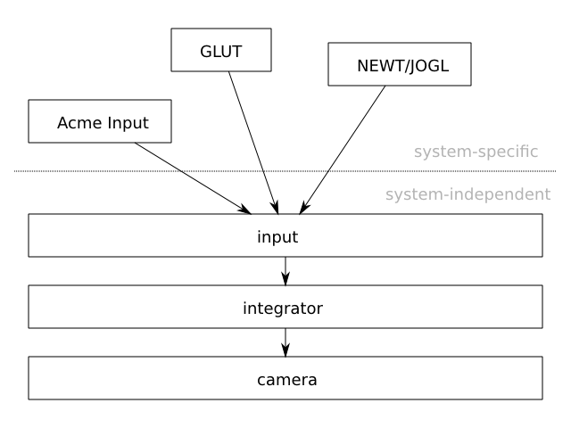
Finally, a system (the input) is described
that actually attaches the camera system to a keyboard and mouse package.
The input package used in the examples is that of
JOGL,
but the system is specifically described in a manner to allow it to
be easily adapted to any other input package. Essentially, the
com.io7m.jcamera
package
tries to provide a cleanly-separated system-independent core, with
the addition of a system to allow it to be attached to system-specific
keyboard/mouse input packages. This is essential for the correctness
of the software and also for the actual ease of understanding of the
mathematics and implementation [1].
Mathematics
Rather than rely on untyped and ambiguous mathematical notation, this
documentation expresses all mathematics in strict
Haskell 2010
with no extensions. All Haskell sources are included along with
the documentation and can therefore be executed from the command
line
GHCi
tool in order to interactively check results and experiment with
functions.
When used within prose, functions are referred to using fully qualified
notation, such as
(Vector3f.cross n t). This
an the application of the cross function
defined in the
Vector3f
module, to the arguments n and
t.
Formal examples and definitions, however, will typically be defined
within their own modules, possibly with import statements used to allow
for shorter names. As an example
[
Forward.hs]:
        module Forward where

import qualified Vector3f

move_forward :: Vector3f.T -> Vector3f.T -> Float -> Vector3f.T
move_forward p forward d = Vector3f.add3 p (Vector3f.scale forward d)
FPS Camera
- 3.2.1. Overview
- 3.2.2. Camera Behaviour
- 3.2.3. Camera Mathematics
- 3.2.4. Camera Implementation
- 3.2.5. Input
- 3.2.6. Integrators
- 3.2.7. Linear Integrators
- 3.2.8. Angular Integrators
- 3.2.9. Aggregate Integrators
Overview
Most modern 3D games and simulations feature a form of camera
known, for want of a better name, as a
first-person-shooter-style free-camera
(subsequently referred to here as fps-style,
for brevity).
The camera is typically controlled by the combination of a mouse
and keyboard and allows the user to orient the view direction using
the mouse, and to move forwards, backwards, left, right, up, and down
using the keyboard.
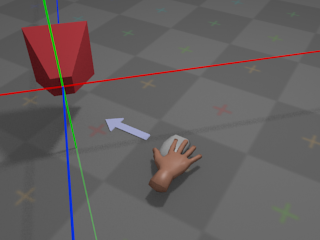
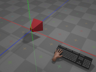
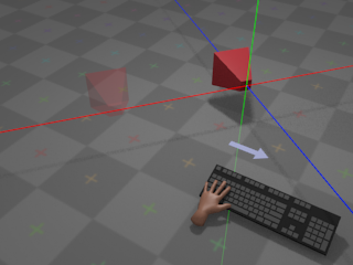
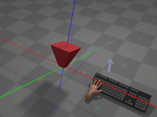
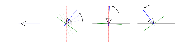
Camera Behaviour
With no input from the mouse, the camera remains at its
current orientation:
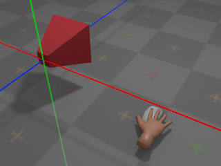
The green line denotes the camera's local Y axis, the red line denotes the
camera's local X axis, and the blue line denotes the camera's local
Z axis.
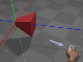
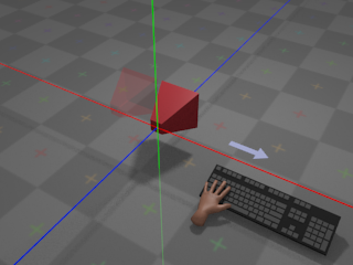
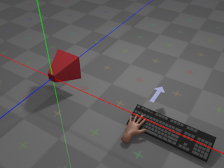
If the user moves the mouse left, the camera will rotate around the
global
Y axis and appear to turn left:
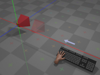
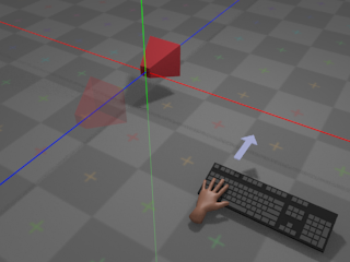
If the user moves the mouse right, the camera will rotate around the
global
Y axis and appear to turn right:
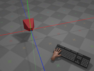
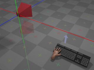
If the user pushes the mouse away,
the camera will rotate around its own local X axis and appear to turn
upwards:
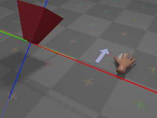
If the user pulls the mouse towards,
the camera will rotate around its own local X axis and appear to turn
downwards:
The choice of whether towards and
away
mean "look down" and "look up",
or "look up" and "look down", respectively, is a matter
of personal taste. Most games and simulations provide an option to
invert the Y axis for mouse control, so that moving the mouse
away
results in the camera turning
downwards, and so on.
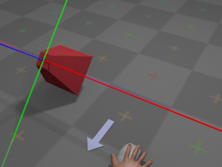
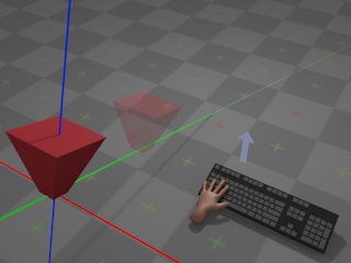
With no input from the keyboard, the camera remains at its
current position:
If the user presses whatever key is assigned to
right,
the camera moves towards positive infinity along its own local
X axis at a configurable rate:
If the user presses whatever key is assigned to
left,
the camera moves towards negative infinity along its own local
X axis at a configurable rate:
Note that movement occurs along the local X
axis; if the camera has been
rotated
around
the global Y axis, then the local X axis has been transformed as a result,
and movement will occur along a different trajectory than in the unrotated
case:
If the user presses whatever key is assigned to
forward,
the camera moves towards negative infinity along its own local
Z axis at a configurable rate:
Whether forward is considered to be towards
positive
or
negative
infinity on the Z axis is more or less a property of the coordinate system
used by the rendering system. Systems such as
OpenGL
traditionally
use a right-handed coordinate system, with
forward
pointing towards negative infinity. Systems
such as
Direct3D
traditionally use a left-handed coordinate
system, with
forward
pointing towards positive infinity. The
com.io7m.jcamera
package assumes a
right-handed
coordinate system.
As with movement on the
local X axis,
forward/backward movement occurs on the camera's local Z axis and is
therefore affected by
rotation around the Y axis.
Finally, if the user presses whatever key is assigned
to up,
the camera moves towards positive infinity along its local Y axis (with
down
moving the camera towards negative infinity, accordingly):

Note that up and
down
movement occurs on the local Y axis and is therefore affected by the
current orientation
of the camera:
All other movement is restricted. The camera cannot, for example, rotate
around its own local Z axis (the roll rotation,
in aircraft terminology).
The rest of this section attempts to give a mathematical description
of a camera system that implements the above behaviour, and describes
the design and implementation of the camera system derived from the
description as it exists in the
com.io7m.jcamera
package.
Camera Mathematics
An fps-style camera can be represented
as a 3-tuple (p, h, v), where
p
is the position of the camera,
h
is an angle around the
camera's local X axis in radians, and
v
is an angle around the
global Y axis in radians. In order to implement forward/backward and
left/right movement (and to derive a final
view matrix
so that the camera
can be used to produce a viewing transform for 3D graphics), it's
necessary to derive a 3-tuple of orthonormal
direction vectors
(forward, right, up)
from the angles h and
v.
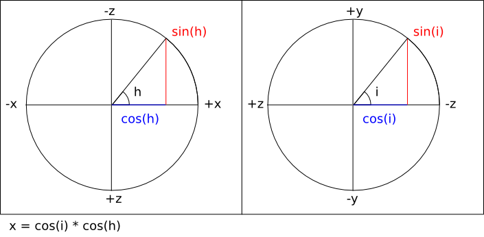
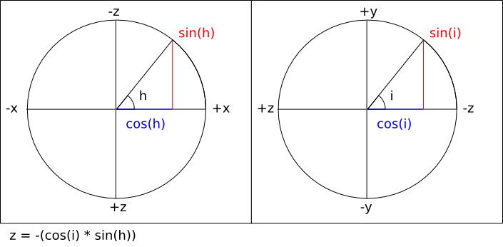
Given the standard trigonometric functions:
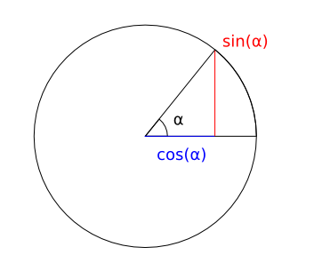
It's possible to calculate the three components of the
forward
vector by assigning
pairs of axes to the unit circle and using three equations:
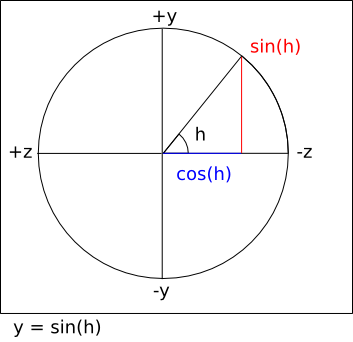
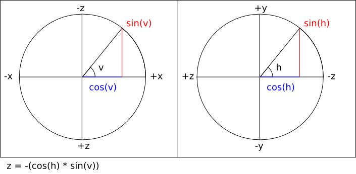
Note that the sign of the right hand side of the last equation
is inverted in order to take into account the fact that the
viewing direction is towards negative Z.
In most mathematics texts, a positive rotation around an axis
represents a counter-clockwise rotation when viewing the system along
the negative direction of the axis in question. Adhering to this
convention, the equations for calculating the
right
vector are identical
except for the fact that the equations work with a value of
v - (π / 2)
instead of
v
(a clockwise rotation
of 90°).
Finally, calculating the
up
vector is simply a matter of calculating the cross product
cross (right, forward).
The com.io7m.jcamera package
assumes that a camera with no rotation or translation applied is
placed at the origin position
p = (0, 0, 0)
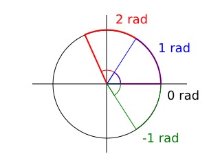
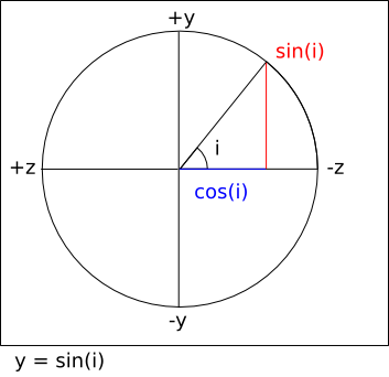
with h = 0 and
v = π / 2. The reason for the
value of v is that in most
mathematics texts, an angle of
0
radians is illustrated as pointing to the right:
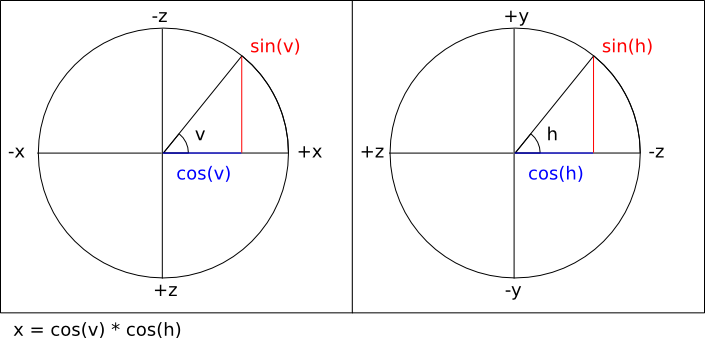
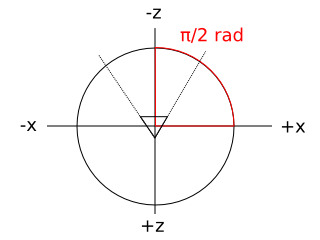
In a typical OpenGL configuration, the viewer is placed at the
origin looking towards negative infinity on the Z axis, and the X
axis appears to run horizontally, perpendicular to the viewing
direction. Given this convention, it's somewhat intuitive to map
those axes to the unit circle as follows (assuming a second observer
looking down onto the scene towards negative infinity on the Y axis):
Using this convention means that the values derived from the vector
equations above can be used directly to compute a
view matrix
in the coordinate
system conventionally used by OpenGL.
As a concrete example, using the default position and orientation
given above, the resulting vectors are calculated as
[
ExampleDefaultVectors.hs]:
        module ExampleDefaultVectors where

import qualified Vector3f

h :: Float
h = 0

v :: Float
v = pi / 2.0

p :: Vector3f.T
p = Vector3f.V3 0.0 0.0 0.0

forward_x :: Float
forward_x = cos (v) * cos (h)
--        = cos (π / 2) * cos (0)
--        = 0 * 1
--        = 0

forward_y :: Float
forward_y = sin (h)
--        = sin (0)
--        = 0

forward_z :: Float
forward_z = -(cos (h) * sin (v))
--        = -(cos (0) * sin (π / 2))
--        = -(1 * 1)
--        = -1

forward :: Vector3f.T
forward = Vector3f.V3 forward_x forward_y forward_z
--      = (0, 0, -1)

right_x :: Float
right_x = cos (v - (pi / 2.0)) * cos (h)
--      = cos (0) * cos (0)
--      = 1 * 1
--      = 1

right_y :: Float
right_y = sin (h)
--      = sin (0)
--      = 0

right_z :: Float
right_z = -(cos (h) * sin (v - (pi / 2)))
--      = -(cos (0) * sin (0))
--      = -(1 * 0)
--      = 0

right :: Vector3f.T
right = Vector3f.V3 right_x right_y right_z
--    = (1, 0, 0)

up :: Vector3f.T
up = Vector3f.cross right forward
-- = ((right_y * forward_z) - (right_z * forward_y),
--    (right_z * forward_x) - (right_x * forward_z),
--    (right_x * forward_y) - (right_y * forward_x))
-- = ((0 * -1) - (0 * 0),
--    (0 * 0) - (1 * -1),
--    (1 * 0) - (0 * 0))
-- = (0, 1, 0)
The resulting forward,
right, and
up
vectors are consistent with the
Z,
X,
and Y axes typically used in
OpenGL.
With the forward and
right
vectors calculated, it is
now trivial to derive forward/backward and left/right movement. Forward
movement by d units is simply a
positive translation of the camera position
p
along the
forward
vector by d units
[
Forward.hs]:
        module Forward where

import qualified Vector3f

move_forward :: Vector3f.T -> Vector3f.T -> Float -> Vector3f.T
move_forward p forward d = Vector3f.add3 p (Vector3f.scale forward d)
A backward movement is simply the same equation with a negative
d
distance:
        module Backward where

import qualified Vector3f
import qualified Forward

move_backward :: Vector3f.T -> Vector3f.T -> Float -> Vector3f.T
move_backward p forward d = Forward.move_forward p forward (-d)
Moving right is a positive translation of the camera position
p
along the
right
vector by d units:
        module Right where

import qualified Vector3f

move_right :: Vector3f.T -> Vector3f.T -> Float -> Vector3f.T
move_right p right d = Vector3f.add3 p (Vector3f.scale right d)
Moving left is simply the same equation with a negative
d
distance:
        module Left where

import qualified Vector3f
import qualified Right

move_left :: Vector3f.T -> Vector3f.T -> Float -> Vector3f.T
move_left p right d = Right.move_right p right (-d)
Moving up is a positive translation of the camera position
p
along the
up
vector by d units:
        module Up where

import qualified Vector3f

move_up :: Vector3f.T -> Vector3f.T -> Float -> Vector3f.T
move_up p up d = Vector3f.add3 p (Vector3f.scale up d)
Moving down is simply the same equation with a negative
d
distance:
        module Down where

import qualified Vector3f
import qualified Up

move_down :: Vector3f.T -> Vector3f.T -> Float -> Vector3f.T
move_down p up d = Up.move_up p up (-d)
The right,
up, and
forward
vectors form an orthonormal
basis for a coordinate system. In practical terms, they provide the
rotational component for a combined rotation and translation that can
be used to transform arbitrary coordinates given in
world space
to
eye space
(also known as
view space). This is what allows the
camera system to actually be used as a camera in 3D simulations. A
matrix that rotates vectors according to the calculated camera vectors
is given by
[
ViewRotation.hs]:
module ViewRotation where
import qualified Matrix4f
import qualified Vector3f
import qualified Vector4f
import Vector3f (x, y, z)
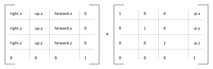
rotation :: (Vector3f.T, Vector3f.T, Vector3f.T) -> Matrix4f.T
rotation (right, up, forward) =
Matrix4f.T {
Matrix4f.column_3 = Vector4f.V4 0.0 0.0 0.0 1.0,
Matrix4f.column_2 = Vector4f.V4 (x forward) (y forward) (z forward) 0.0,
Matrix4f.column_1 = Vector4f.V4 (x up) (y up) (z up) 0.0,
Matrix4f.column_0 = Vector4f.V4 (x right) (y right) (z right) 0.0
}
A matrix that translates vectors according to the current camera
position is given by
[
ViewTranslation.hs]:
        module ViewTranslation where

import qualified Matrix4f
import qualified Vector3f
import qualified Vector4f
import Vector3f (x, y, z)

translation :: Vector3f.T -> Matrix4f.T
translation p =
  let np_x = -(x p)
      np_y = -(y p)
      np_z = -(z p)
  in
    Matrix4f.T {
      Matrix4f.column_3 = Vector4f.V4 np_x np_y np_z 1.0,
      Matrix4f.column_2 = Vector4f.V4 0.0  0.0  1.0  0.0,
      Matrix4f.column_1 = Vector4f.V4 0.0  1.0  0.0  0.0,
      Matrix4f.column_0 = Vector4f.V4 1.0  0.0  0.0  0.0
    }
        module View where

import ViewTranslation (translation)
import ViewRotation (rotation)
import qualified Matrix4f
import qualified Vector3f

view_matrix :: Vector3f.T -> (Vector3f.T, Vector3f.T, Vector3f.T) -> Matrix4f.T
view_matrix p (right, up, forward) =
  Matrix4f.mult (rotation (right, up, forward)) (translation p)
Camera Implementation
In the com.io7m.jcamera package,
the interface exposed by an fps-style camera
is described by the
JCameraFPSStyleType
type. The actual implementation of the
camera mathematics
is given in the
JCameraFPSStyle
type.
A small point to note about the implementation:
The
forward, right, and
up
vectors are calculated lazily whenever the user attempts
to perform an operation that involves them. The vectors are derived only
from the current camera
angles and so are not recomputed if the angles have not been changed since
the vectors were
last calculated.
Input
In the com.io7m.jcamera package,
an input is a simple abstraction intended
to keep
integrators
insulated from the platform-specific details of keyboard and mouse input.
With the
behaviour
described in the first subsection, there are two types of input:
Discrete
input (where the user presses
a key and the input is assumed to be constant until the key is released)
and continuous input (where the user
moves a mouse and a stream of new mouse position vectors are generated).
Discrete input can be represented by a simple boolean flag, and continuous
input can be represented by summing the received input until an
integrator is ready to receive it.
        module Input (T (..)) where

data T = T {
  is_moving_backward  :: Bool,
  is_moving_forward   :: Bool,
  is_moving_left      :: Bool,
  is_moving_right     :: Bool,
  is_moving_up        :: Bool,
  is_moving_down      :: Bool,
  rotation_horizontal :: Float,
  rotation_vertical   :: Float
} deriving (Eq, Show)
When the user presses whatever is key assigned to
up, the corresponding boolean field in
the data structure is set to true. When
the user releases the key, the corresponding field is set to
false.
The situation for mouse movement is slightly more complex. Most
OS-specific
windowing systems will provide the user with the current mouse cursor
coordinates
as a pair of integer offsets (in pixels) relative to some origin. Some
systems
have the origin (0, 0) at the
top-left corner of the
screen/window, whilst others have it at the bottom-left corner of the
window.
Additionally, the density of displays is increasing at a steady rate. A
monitor
manufactured five years ago may be 40cm wide and have a resolution that
fits
1440 pixels into that width. A modern display may be the same width but
have
over four times as many pixels in the same space. A camera system that
recklessly consumes coordinates given in pixels is going to behave
differently
on a screen that has a higher density of pixels than it would on an older,
lower
resolution display.
In order for the com.io7m.jcamera package
to remain system-independent, it's necessary to provide a way to map mouse
input
to a simple and consistent set of generic
rotation coefficients
that can be consumed by an
integrator. The rotation coefficients are a pair of values
(rx, ry)
expressing the intention to rotate
the camera, with
rx
affecting rotation around the camera's vertical axis, and
ry
affecting rotation around the camera's horizontal axis. In effect, when
rx == -1.0, the camera should appear
to
rotate
right
[2]
. When rx == 1.0,
the camera should appear to rotate left.
When
ry == 1.0, the camera should appear
to rotate
up. When ry ==
-1.0,
the camera should appear to rotate down.
The
coefficients linearly express fractional rotation, so a rotation of
0.5
is exactly half as much rotation as
1.0.
The scheme used to map screen positions to coefficients is as follows:
- When the mouse cursor is in the exact center of the screen, the resulting rotation coefficients are (0, 0).
- When the mouse cursor is in the uppermost, rightmost position of the screen q, the resulting rotation coefficients are (-1.0, 1.0).
- When the mouse cursor is in the lowermost, leftmost position of the screen p, the resulting rotation coefficients are (1.0, -1.0).
- The rotation coefficients for any other position on the screen can be derived from simple linear interpolation between p and q.
In order to actually map screen positions to rotation coefficients, it's
necessary
to take into account the windowing-system-specific origin. It's necessary
to define
a function that takes a mouse region representing
the width and height of the screen with information labelling the origin,
and a pair
of screen/window-space coordinates (sx,
sy), and
returns a pair of rotation coefficients
[
MouseRegion.hs]:
        module MouseRegion (T, newRegion, coefficients) where

data Origin =
    TopLeft
  | BottomLeft
    deriving (Eq, Show)

data T = T {
  origin   :: Origin,
  width    :: Float,
  height   :: Float,
  center_x :: Float,
  center_y :: Float
} deriving (Eq, Show)

newRegion :: Origin -> Float -> Float -> T
newRegion o w h = T {
  origin   = o,
  width    = w,
  height   = h,
  center_x = w / 2.0,
  center_y = h / 2.0
}

coefficients :: T -> (Integer, Integer) -> (Float, Float)
coefficients r (sx, sy) =
  let fx = fromIntegral sx
      fy = fromIntegral sy
      ox = ((fx - center_x r) / width r) * 2.0
      oy = ((fy - center_y r) / height r) * 2.0
  in
    case (origin r) of
      TopLeft    -> (-ox, -oy)
      BottomLeft -> (-ox, oy)
The assumption here is that the mouse cursor will be
warped
back to the center of the screen at periodic
intervals. If this did not occur, the mouse cursor would eventually reach
one or
more edges of the screen and would be unable to travel further, halting
any rotation
in those directions.
In event-based windowing systems, every
time the
user moves the mouse, a mouse event is
generated
containing the current cursor position. In some systems, the user must
explicitly
ask for the current mouse position when it is needed. In the former case,
new
rotation coefficients will be generated repeatedly. In the latter case,
the
user will typically ask for the current mouse position at the beginning of
rendering the current simulation frame, and therefore will only receive a
single
set of coefficients (effectively representing the furthest distance that
the mouse
travelled during that time period). In the
com.io7m.jcamera
package, an
integrator
will
read (and reset to (0.0, 0.0))
the current rotation coefficients from an input at a (typically) fixed
rate. The current rotation coefficients stored in an input therefore
represent the sum of mouse movements for a given elapsed time period. To
this
end, the
JCameraFPSStyleInput
type in the com.io7m.jcamera package
provides
an interface where the user simply submits new rotation coefficients each
time
they are received, and the type keeps a running total of the coefficients.
This
allows the input system to work the same way regardless of whether the
user
has to ask for mouse input, or is receiving it piecemeal via some event
system.
By taking the width and height of the screen in pixels, and dividing as
shown in the above equations, the resulting coefficients are
screen-density independent. In other words,
if the user moves the cursor halfway across the screen on a very high
density display, the resulting coefficients are the same as those
resulting
from a user moving the cursor across the same distance on a much lower
density display, even though the distances expressed in pixels are very
different.
In the com.io7m.jcamera package,
fps-style inputs are represented by the
JCameraFPSStyleInput
type, and mouse regions are represented by the
JCameraFPSStyleMouseRegion
type.
Integrators
Linear Integrators
A linear integrator updates the position
of a camera over time.
In physics, the first derivative of
position
with respect to time is
velocity. The second derivative of
position with respect to time is
acceleration.
Newton's second law of motion relates force
f
with mass m and acceleration
a
[
SecondLaw.hs]:
        module SecondLaw where

f :: Float -> Float -> Float
f m a = m * a
Rearranging the equation, acceleration is given in terms of
[
SecondLawRewrite.hs]:
        module SecondLawRewrite where

a :: Float -> Float -> Float
a f m = (1 / m) * f
However, if m is assumed to
be 1,
a = (1 / 1) * f = f. So, rather than
assign mass
to a camera and try to apply forces, it's possible to simply apply
acceleration
as a (configurable) constant term directly. Linear integrators in the
com.io7m.jcamera
package are
represented as 8-tuples
(a, c, d, i, ms, sf, sr, su)
where:
- a is the acceleration to be applied, given in units-per-second-per-second.
- c is the camera to be affected.
- d is the drag factor.
- i is an input.
- ms is the maximum speed for the camera, in units-per-second.
- sf current forward speed of the camera, in units-per-second.
- sr current right speed of the camera, in units-per-second.
- su current up speed of the camera, in units-per-second.
The meaning of units mentioned above is
application specific. An application might choose to map units to meters,
or miles, or any other arbitrary measure of distance.
As mentioned, an integrator makes changes to the position and orientation
of a camera over a given delta time period.
In most simulations, the camera will be updated at a fixed rate of
something
approaching 60 times per second. The
delta
time in this case would be given by
delta = 1.0 / 60.0 = 0.0166666....
The
integrator calculates a speed for each of the three
(right, up, forward)
axes in turn based
on the current linear acceleration/deceleration values, and the data from
the associated input, and
tells the associated camera to move based on the resulting speeds.
For the forward axis, the integrator
calculates a forward speed sfr based
on the previous forward speed sf, the
state of the input i, the
acceleration a, and the drag factor
d, and increases the camera position
by
sfr
units along the forward axis. The
forward speed is clamped to the configurable range
[-ms, ms].
Specifically, the procedure is given by
[
IntegratorForward.hs]:
        module IntegratorForward where

import qualified Clamp
import qualified Vector3f
import qualified Input

forward_speed :: Input.T -> Float -> Float -> Float -> Float
forward_speed i sf a delta =
  if (Input.is_moving_forward i)
  then sf + (a * delta)
  else sf

backward_speed :: Input.T -> Float -> Float -> Float -> Float
backward_speed i sf a delta =
  if (Input.is_moving_backward i)
  then sf - (a * delta)
  else sf

forward :: (Vector3f.T, Vector3f.T, Float, Input.T, Float, Float, Float) -> Float -> (Vector3f.T, Float)
forward (p, v_forward, sf, i, a, d, ms) delta =
  let
    sf0 = backward_speed i (forward_speed i sf a delta) a delta
    sf1 = Clamp.clamp sf0 (-ms, ms)
    pr  = Vector3f.add3 p (Vector3f.scale v_forward (sf1 * delta))
    sfr = sf1 * (d ** delta)
  in
    (pr, sfr)
The drag factor is a configurable value
that specifies how the camera will slow down over time. Ideally, when the
user is not telling the camera to move, the camera is either stationary
or on its way to becoming stationary. A drag factor
d
will result in a speed
s'
by
s' = s * (d ** delta). Intuitively,
the drag factor can be seen as the fraction of the original speed that
will remain after one second of not receiving any acceleration. If
d = 0.0, any object not having
acceleration applied will immediately stop. If
d = 1.0, an object will continue
moving indefinitely
[3]. A drag factor of 0.0 will
also imply an overall movement speed penalty due to the way integration is
performed. Usually, a drag factor of
0.0
is a bad idea - values closer to
0.0001
give the same abrupt behaviour but with slightly smoother results and less
of a movement speed penalty.
Integration for the other axes is identical, modulo the parts of the
input
that are sampled
[
IntegratorRight.hs]
and
[
IntegratorUp.hs]:
        module IntegratorRight where

import qualified Clamp
import qualified Vector3f
import qualified Input

right_speed :: Input.T -> Float -> Float -> Float -> Float
right_speed i sf a delta =
  if (Input.is_moving_right i)
  then sf + (a * delta)
  else sf

left_speed :: Input.T -> Float -> Float -> Float -> Float
left_speed i sf a delta =
  if (Input.is_moving_left i)
  then sf - (a * delta)
  else sf

right :: (Vector3f.T, Vector3f.T, Float, Input.T, Float, Float, Float) -> Float -> (Vector3f.T, Float)
right (p, v_right, sf, i, a, d, ms) delta =
  let
    sf0 = left_speed i (right_speed i sf a delta) a delta
    sf1 = Clamp.clamp sf0 (-ms, ms)
    pr  = Vector3f.add3 p (Vector3f.scale v_right (sf1 * delta))
    sfr = sf1 * (d ** delta)
  in
    (pr, sfr)
        module IntegratorUp where

import qualified Clamp
import qualified Vector3f
import qualified Input

up_speed :: Input.T -> Float -> Float -> Float -> Float
up_speed i sf a delta =
  if (Input.is_moving_up i)
  then sf + (a * delta)
  else sf

down_speed :: Input.T -> Float -> Float -> Float -> Float
down_speed i sf a delta =
  if (Input.is_moving_down i)
  then sf - (a * delta)
  else sf

up :: (Vector3f.T, Vector3f.T, Float, Input.T, Float, Float, Float) -> Float -> (Vector3f.T, Float)
up (p, v_up, sf, i, a, d, ms) delta =
  let
    sf0 = down_speed i (up_speed i sf a delta) a delta
    sf1 = Clamp.clamp sf0 (-ms, ms)
    pr  = Vector3f.add3 p (Vector3f.scale v_up (sf1 * delta))
    sfr = sf1 * (d ** delta)
  in
    (pr, sfr)
The type of linear integrators in the
com.io7m.jcamera
is
JCameraFPSStyleLinearIntegratorType,
with the default implementation being
JCameraFPSStyleLinearIntegrator.
Angular Integrators
An angular integrator updates the
orientation
of a camera over time.
Integration of orientation occurs in almost exactly the same manner as
integration of
position;
orientation is treated as a pair of scalar rotations around two axes, and
the
rotation values are increased by speed values calculated from acceleration
values for each axis. Integration of rotations around the vertical axis is
given by
[
IntegratorAngularVertical.hs]:
        module IntegratorAngularVertical where

import qualified Clamp
import qualified Input

vertical :: (Float, Float, Input.T, Float, Float, Float) -> Float -> (Float, Float)
vertical (v, sv, i, a, d, ms) delta =
  let
    sf0 = sv + ((Input.rotation_vertical i) * a * delta)
    sf1 = Clamp.clamp sf0 (-ms, ms)
    vr  = v + (sf1 * delta)
    sfr = sf1 * (d ** delta)
  in
    (vr, sfr)
Note that the acceleration around the axis is multiplied by the
rotation
coefficients
taken from the input.
Rotation around the horizontal axis is identical, except that the actual
camera itself may clamp rotations around
the horizontal axis. The reason for this is simple: If rotations are not
clamped, and the user rotates the camera upwards or downwards, there comes
a point where the camera's rotation value wraps around and the camera
begins
to rotate in the opposite direction, as illustrated:
The practical result of the above wrapping is that the user would, for
example,
be rotating the camera up towards the ceiling, the camera would reach the
limit
of rotation, and suddenly the camera would be facing the opposite
direction
and rotating down towards the floor again. This behaviour would be
irritating,
so cameras may optionally clamp rotations
and are required to indicate when clamping occurs so that the integrator
can
zero the speed of rotation around that axis. The reason for the zeroing of
the rotation speed is that if the speed were not zeroed, and the rotation
around the axis was proceeding at, say,
100
radians per second, the user would have to cause the rotation to decrease
by over 100 radians per second in the
opposite direction in order to get the camera to rotate at all. In effect,
the camera would appear to reach the limit of rotation, stop, and then the
user would have to scrub the mouse repeatedly in the opposite direction
in order to get rotation to begin again in the opposite direction.
The type of angular integrators in the
com.io7m.jcamera
is
JCameraFPSStyleAngularIntegratorType,
with the default implementation being
JCameraFPSStyleAngularIntegrator.
Aggregate Integrators
Usually, a user will want cameras to both move and rotate, as
opposed to just one or the other. The
com.io7m.jcamera
package
provides the
JCameraFPSStyleIntegratorType
which aggregates both the
linear
and
angular
integrators, with the default implementation given by
JCameraFPSStyleIntegrator.
Spherical Camera
- 3.3.1. Overview
- 3.3.2. Camera Behaviour
- 3.3.3. Camera Mathematics
- 3.3.4. Camera Implementation
- 3.3.5. Input
- 3.3.6. Integrators
- 3.3.7. Linear Integrators
- 3.3.8. Angular Integrators
- 3.3.9. Aggregate Integrators
Overview
Most real-time strategy games implement some variation of a
so-called spherical camera (also
sometimes known as an orbital camera).
A spherical camera always points towards, and stays a given distance
from, a target point.
One of the classic examples of this type of camera was implemented
in Bungie's
Myth II: Soulblighter.
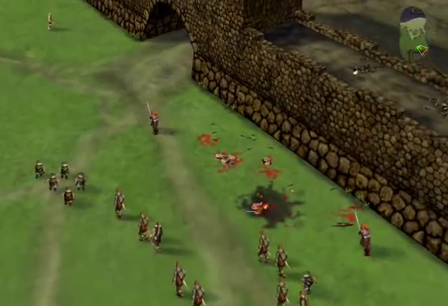
The camera described here implements a useful subset of the
capabilities of Myth II's camera
system
[4]
.
A restricted form of this camera is present in Blizzard's
Starcraft II.
The mouse-control scheme for
Starcraft's
camera is generally considered to be the definitive one amongst
real-time strategy games, and the camera described here shamelessly
duplicates it.
It is recommended that the reader fully understand the implementation
and mathematics of
fps-style cameras
as most of the implementation described here uses the same approach
and concepts.
Camera Behaviour
A spherical camera remains at a given radius
from
a movable target point. The orientation of
the
camera is derived from a heading angle and
an
incline
angle.
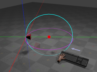
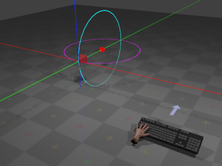
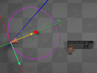
With no input from the mouse, the camera remains at its
current orientation:
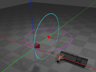
The red sphere indicates the target point.
The camera remains at a given radius from
the target point, with the cyan ring indicating the path that the camera
would take if the incline were to change,
and the magenta ring indicating the path that the camera would take if
the heading were to change. If the user
presses the whatever key is assigned to orbit
left,
the camera heading angle begins to
decrease
at a configurable rate.
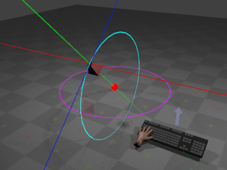
This results in the camera rotating horizontally around the target point:
If the user presses whatever key is assigned to
orbit right,
the camera begins to rotate around the same arc but in the opposite
direction.
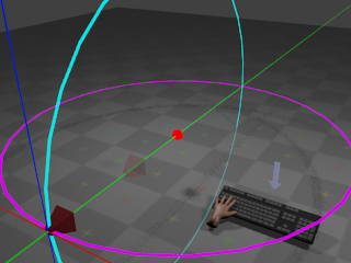
If the user presses whatever key is assigned to
orbit up,
the camera incline angle begins to
increase
at a configurable rate. This results in
the camera rotating vertically around the target point:
If the user presses whatever key is assigned to
orbit down,
the camera begins to rotate around the same arc but in the opposite
direction.
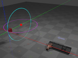
If the user presses whatever key is assigned to zoom
out,
the radius begins to increase at a
configurable
rate. This results in the camera giving the effect of
zooming out:
If the user presses whatever key is assigned to zoom
in,
the radius begins to decrease at a
configurable
rate. This results in the camera giving the effect of
zooming in.
The target point can also move according to
user input:
Whether target point movement occurs due to keyboard or mouse input is
a matter of taste. The implementation described here provides both.
Movement
of the target point occurs along directions derived from the camera's
current
orientation. When the user instructs the target point to move
up, the point begins to move towards
positive infinity on the global Y axis. When the user instructs the target
point to move forward, the target point
begins
to move along the direction defined by projecting the camera's current
forward
vector onto the horizontal plane.
When the user instructs the target
point to move right, the target point
begins
to move along the direction defined by projecting the camera's current
right
vector onto the horizontal plane.
The precise definitions of these vectors are given in the following
section
on the mathematics of the camera.
Moving the target point via keyboard input works in a familiar and
unsurprising manner: When the user presses whatever key is assigned
to a particular direction, the camera moves in that direction until
the user releases the key.
Moving the target point via mouse input is more complicated, however.
Mouse movement is provided by both
dragging
and edge scrolling. When the user
drags
the mouse in a given direction,
the camera appears to move in the opposite direction by an amount
proportional to the drag distance. When the user moves the mouse
cursor to the edge of the screen,
the camera appears to move in at a constant rate in a direction
relative to the edge of the screen, until the user moves the mouse
cursor away from that edge. These descriptions are somewhat vague,
and a more formal description is given in the section on
camera mathematics.
Camera Mathematics
A spherical camera can be represented
as a 4-tuple (t, h, i, r), where
t
is the position of the target point,
h
is an angle around the
global Y axis (the heading),
i
is an angle around the
local X axis in radians (the incline),
and r is the camera's distance
from the target point (the radius). Astute
readers will notice that the defined angles are coordinates in a
spherical coordinate system,
and therefore the movement of the camera around the target point
always describes a sphere of radius r.
As with
fps-style
cameras, in order to implement forward/backward and
left/right movement (and to derive a final
view matrix
so that the camera
can be used to produce a viewing transform for 3D graphics), it's
necessary to derive a 3-tuple of orthonormal
direction vectors
(forward, right, up)
from the camera's angles and radius.
In order to derive the vectors, it's necessary to first work out
the orientation of the camera. In order to calculate a full viewing
transform, it's also necessary to calculate the actual world-space
position p of the camera.
As stated in the description of the
camera behaviour,
the camera is always oriented towards
t.
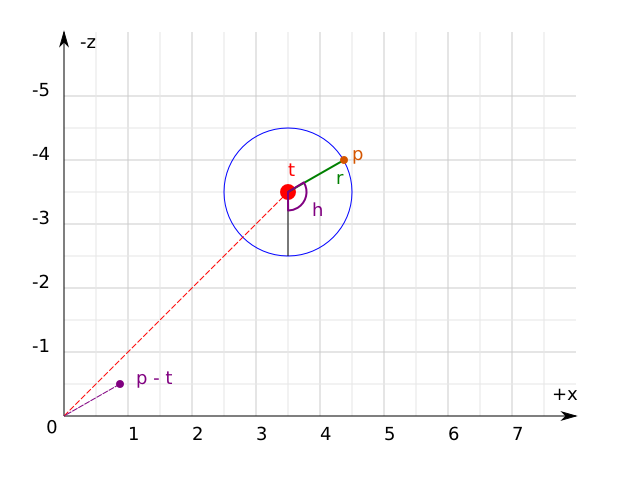
The mathematics of determining the camera's world-space position and
orientation can
be simplified if t is considered as
the origin of a new local coordinate system that will be referred to as
target-space. Transforming a world-space
position w to
target-space simply requires subtracting
t
from w. Transforming a target-space
position u to world-space requires
adding t to
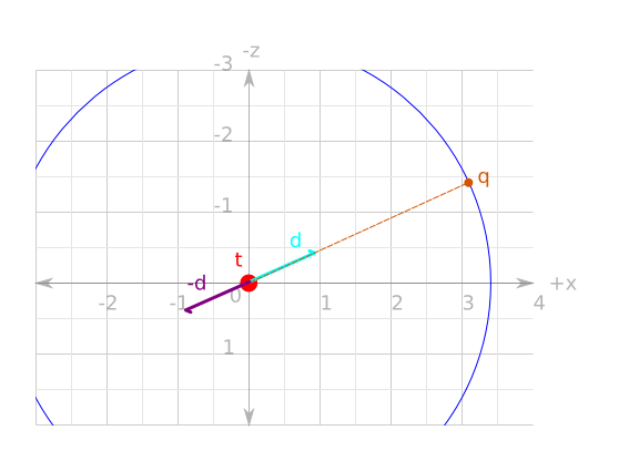
u. The following diagram illustrates
all of the above, flattened onto the X/Z (horizontal) plane for ease of
viewing:
Firstly, then, to calculate the target-space camera position
q
the same equations are
used as were used when calculating the
direction vectors
for the fps-style camera. Firstly, a direction vector
d
is calculated
that points towards q from the
origin:
Then, q is simply
d
scaled by
r:
q = Vector3f.scale d r
The world-space camera position
p
is simply q added to
t:
p = Vector3f.add3 q t
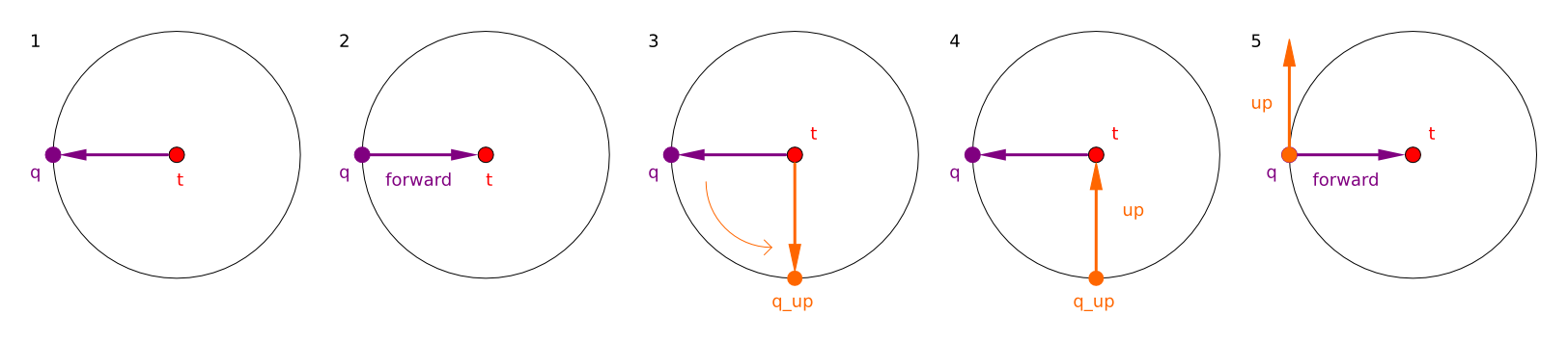
As stated, the aim is to construct a
forward
vector that points
towards t from
p. This is simply
the negation of d:
forward = Vector3f.normalize (Vector3f.scale d -1)
Constructing the
up
vector for the
camera is achieved by performing the exact same calculation
as for the forward vector
but with i - (π / 2).
Intuitively, this works by calculating
q
as if it had been orbited
downwards around the sphere, and then taking the negation
of the resulting direction vector as normal:
Finally, calculating the right vector is
simply the cross product of the forward and
up
vectors.
right = Vector3f.cross forward up
As stated earlier, forward/backward and left/right movement
occurs only on the horizontal plane. Because the camera is
not allowed to roll, the calculated
right
vector is always parallel
to the horizontal plane and can therefore be used directly. Because
the camera inclination is variable, however, the calculated
forward
vector is only parallel
to the horizontal plane when i = 0.
It's therefore necessary to calculate a
forward_on_xz
vector that is always
parallel to the horizontal plane. This is achieved by projecting
the forward vector onto the X/Z
plane via a simple orthographic projection:
project :: Vector3f.T -> Vector3f.T
project v =
  let vx = Vector3f.x v
      vz = Vector3f.z v
  in Vector3f.normalize (Vector3f.V3 vx 0.0 vz)

forward_on_xz :: Vector3f.T
forward_on_xz = project forward
There is an issue here: The projection of the forward vector resulting
from an incline of exactly
(π / 2)
or (-π / 2) radians results in a
forward
vector equal to
(0, ±1, 0), the projection of which
is the zero vector (0, 0, 0). This
means that when the camera is looking directly up towards (or directly
down upon)
the target position, the camera cannot be moved forwards or backwards.
In practice, it is rare that the incline will be exactly either these
values. The problem can be worked around entirely by clamping the possible
incline ranges to [(π / 2) + e, (-π / 2) -
e],
where e is an arbitrary very small
value.
A complete listing of all the equations given so far, using
the default inclination and heading angles, and the default
camera position is as follows
[
ExampleSphericalDefaultVectors.hs]:
        module ExampleSphericalDefaultVectors where

import qualified Vector3f

heading :: Float
heading = -pi / 2.0

incline :: Float
incline = 0

radius :: Float
radius = 8

target :: Vector3f.T
target = Vector3f.V3 0 1 4

direction :: Float -> Float -> Vector3f.T
direction heading incline =
  let
    x = (cos heading) * (cos incline)
    y = sin incline
    z = -((cos incline) * (sin heading))
  in
    Vector3f.V3 x y z

d :: Vector3f.T
d = direction heading incline

q :: Vector3f.T
q = Vector3f.scale d radius

p :: Vector3f.T
p = Vector3f.add3 q target

forward :: Vector3f.T
forward = Vector3f.normalize (Vector3f.scale d (-1.0))

up :: Vector3f.T
up =
  let d = direction heading (incline - (pi / 2.0)) in
    Vector3f.normalize (Vector3f.scale d (-1.0))

right :: Vector3f.T
right = Vector3f.cross forward up

project :: Vector3f.T -> Vector3f.T
project v =
  let vx = Vector3f.x v
      vz = Vector3f.z v
  in Vector3f.normalize (Vector3f.V3 vx 0.0 vz)

forward_on_xz :: Vector3f.T
forward_on_xz = project forward
Movement of the target point is achieved identically to the
way
fps-style cameras
move, except that the
forward_on_xz
vector is used instead of the ordinary
forward
vector for forward/backward
movement, and the global Y axis is used for
up/down movement instead of the camera's
up
vector.
View matrix
calculating is also identical, using the calculated
forward,
right,
and up vectors, and
p
for the translational components.
In order to implement
mouse control
over movement of the target point, it's necessary to somehow map
two-dimensional mouse cursor movements to three-dimensional camera
movements. All windowing systems tend to use system-specific
conventions: Some windowing systems place
(0, 0)
at the top-left corner of the
window, and others place (0, 0) at
the bottom-left corner. In order to get
system-independent
and display-density-independent mouse
control,
the com.io7m.jcamera package
borrows
a concept from OpenGL:
normalized device coordinates
(albeit in a two-dimensional form). In normalized
device space,
the origin (0, 0) is in the center of
the screen.
The rightmost edge of the screen is x =
1, the
leftmost edge of the screen is x = -1,
the topmost
edge is y = 1, and the bottommost ege
is
y = -1:
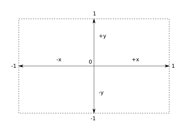
The translation to normalized device coordinates from screen coordinates
is simple, although slightly different equations are needed for systems
that use a top-left origin as opposed to a bottom-left origin
[
NormalizedDevice.hs]:
        module NormalizedDevice where

import qualified Vector3f

width :: Float
width = 640.0

height :: Float
height = 480.0

to_ndc_from_top_left :: (Integer, Integer) -> (Float, Float)
to_ndc_from_top_left (sx, sy) =
  let
    center_x = width / 2.0
    center_y = height / 2.0
    rx = ((fromIntegral sx - center_x) / width) * 2.0
    ry = ((fromIntegral sy - center_y) / height) * 2.0
  in
    (rx, ry)

to_ndc_from_bottom_left :: (Integer, Integer) -> (Float, Float)
to_ndc_from_bottom_left (sx, sy) =
  let
    center_x = width / 2.0
    center_y = height / 2.0
    rx = ((fromIntegral sx - center_x) / width) * 2.0
    ry = ((fromIntegral sy - center_y) / height) * 2.0
  in
    (rx, -ry)
Given an arbitrary cursor position expressed as normalized device
coordinates, it's then possible to determine if the cursor is at
one or more of the screen edges. This is how
edge scrolling
is implemented.
For example, if the cursor is at (1,
1),
then it means the cursor is at the extreme top-right corner of the screen.
The simple fact that a given cursor either is or isn't at a particular
edge
can be used as a discrete input. For the spherical camera described here,
if the
cursor is moved to the top edge of the screen, it is as if the user had
pressed whatever key is assigned to forward.
The camera continues moving in that direction until the cursor is moved
away from the edge. If the cursor is moved to the right edge of the
screen, it is as if the user had pressed whatever key is assigned to
right. If the cursor is at one of the
corners, it is as if the user had pressed whatever keys are assigned
to the two relevant edges.
For the other form of mouse control - dragging
-
the same system is used to map screen-space mouse coordinates to
normalized device coordinates. However, the coordinates of the mouse
are only taken into account when the relevant mouse button is being
held
[5]
. The offsets from the center of the screen are accumulated
in the same manner as with the
rotation
coefficients
for fps-style cameras, and are reset to
(0, 0)
periodically in the same manner. Additionally, the offsets are negated
when the actual camera movement is applied. For example, if the user
has dragged the mouse to the right,
the camera is actually moved left. An
intuitive way to think of this is to imagine that the objects that the
camera is observing are on a sheet, and in order to look at a specific
object that is laying to the right of the camera, the sheet must be
pulled left to move the object into view. This is not actually mandated
by the implementation in the
com.io7m.jcamera
package;
the programmer is free to pass the non-negated offsets to the camera
in order to move it
[6]. An illustration of this (with the red frame indicating
the camera's view):
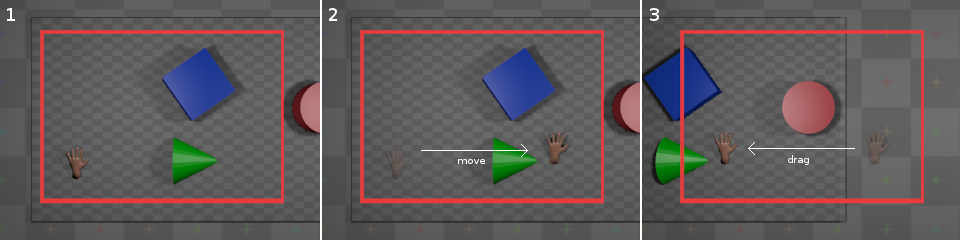
In practical terms, with the default settings, if the user drags the
mouse downward, the camera moves as if
the user had pressed whatever key is assigned to
forward
for the
duration of the drag. If the user drags the mouse
right, the camera moves as if the user
had pressed left for the duration of
the drag. The camera will correctly move diagonally if the user drags
downward
and
right.
Camera Implementation
In the com.io7m.jcamera package,
the interface exposed by a spherical camera
is described by the
JCameraSphericalType
type. The actual implementation of the
camera mathematics
is given in the
JCameraSpherical
type.
A small point to note about the implementation:
The
forward, right, and
up
vectors are calculated lazily whenever the user attempts
to perform an operation that involves them. The vectors are derived only
from the current camera
angles and so are not recomputed if the angles have not been changed since
the vectors were
last calculated.
Input
In the com.io7m.jcamera package,
an input is a simple abstraction intended
to keep
integrators
insulated from the platform-specific details of keyboard and mouse input.
As described in the section on
fps-style camera input,
input can categorized as discrete or
continuous. The details of input for
spherical cameras are slightly more complicated than for fps-style
cameras due to the more complex
control
scheme.
An input for a spherical camera in the
com.io7m.jcamera
package is
represented by the following data structure
[
InputSpherical.hs]:
        module InputSpherical (T (..)) where

data T = T {

  is_moving_backward_key    :: Bool,
  is_moving_backward_cursor :: Bool,

  is_moving_forward_key    :: Bool,
  is_moving_forward_cursor :: Bool,

  is_moving_left_key     :: Bool,
  is_moving_left_cursor  :: Bool,

  is_moving_right_key    :: Bool,
  is_moving_right_cursor :: Bool,

  is_moving_up        :: Bool,
  is_moving_down      :: Bool,

  moving_forward_continuous :: Float,
  moving_right_continuous   :: Float,

  is_orbiting_heading_positive :: Bool,
  is_orbiting_heading_negative :: Bool,
  is_orbiting_incline_positive :: Bool,
  is_orbiting_incline_negative :: Bool,

  is_zooming_in  :: Bool,
  is_zooming_out :: Bool

} deriving (Eq, Show)
In a similar manner to the fps-style
camera input,
pressing a key on the keyboard sets the corresponding boolean field
in the input to true, setting
it to false when the key is released.
In order to account for the fact that some movements can be prompted by
both the keyboard and mouse, there are separate fields for keyboard and
cursor control. For example, moving a mouse to the right edge of the
screen
sets the is_moving_right_cursor field
to true. The
moving_forward_continuous
and
moving_right_continuous
fields
represent the accumulated
dragging
for the current time period.
In the com.io7m.jcamera package,
spherical camera inputs are represented by the
JCameraSphericalInput
type, and mouse regions are represented by the
JCameraSphericalMouseRegion
type.
Integrators
Linear Integrators
A linear integrator updates the position
of a camera over time.
Linear integration of the camera is achieved in an almost identical
manner to linear integration of
fps-style
cameras,
with the addition of the changes of position caused by the continuous
input from mouse
dragging.
Changes in radius (zooming) are also handled by the linear integrator.
Calculation of the forward velocity
is given by the following equations
[
IntegratorSphericalForward.hs]:
        module IntegratorSphericalForward where

import qualified Clamp
import qualified Vector3f
import qualified InputSpherical

forward_speed :: InputSpherical.T -> Float -> Float -> Float -> Float
forward_speed i sf a delta =
  if (InputSpherical.is_moving_forward_key i || InputSpherical.is_moving_forward_cursor i)
  then sf + (a * delta)
  else sf

backward_speed :: InputSpherical.T -> Float -> Float -> Float -> Float
backward_speed i sf a delta =
  if (InputSpherical.is_moving_backward_key i || InputSpherical.is_moving_backward_cursor i)
  then sf - (a * delta)
  else sf

drag_forward_speed :: InputSpherical.T -> Float -> Float -> Float
drag_forward_speed i a delta =
  (InputSpherical.moving_forward_continuous i) * a * delta

forward :: (Vector3f.T, Vector3f.T, Float, InputSpherical.T, Float, Float, Float) -> Float -> (Vector3f.T, Float)
forward (p, v_forward_on_xz, sf, i, a, d, ms) delta =
  let
    sf0 = backward_speed i (forward_speed i sf a delta) a delta
    sf1 = Clamp.clamp sf0 (-ms, ms)
    sd  = drag_forward_speed i a delta
    sf2 = sf1 + sd
    pr  = Vector3f.add3 p (Vector3f.scale v_forward_on_xz (sf2 * delta))
    sfr = sf1 * (d ** delta)
  in
    (pr, sfr)
The first thing to note is the
drag_forward_speed
function: This calculates how much the camera should be moving in the
forward
direction based on the current accumulated continuous input. The forward
speed
calculated by the function is added to the current total speed
after
the total has been
clamped
to the speed limits. The reason for this
is simply that the speed limits are usually set reasonably low in order to
avoid
the camera getting up to too high a speed when controlled by the keyboard,
but
the low speed limits also tend to mean that the user cannot drag the mouse
fast enough
to get a comfortable movement rate. Exceeding the speed limit temporarily
is mildly
distasteful, but relies on the fact that the user is physically limited by
their own
ability to fling a piece of plastic across a desktop, and so the speed of
the camera
should not become excessively high. An alternate solution would be to have
two sets
of speed limits, one for keyboard control and another for dragging. This
is trivial
to implement, but is not implemented here for the sake of keeping the
implementation
as easy to understand as possible.
There is also a limitation in the described integrator: The camera feels
increasingly
sluggish as the camera zooms out. This is purely a perceptual issue: If
the camera
is a very long way away from an object, then the camera has to move much
further
for there to be a perceived movement onscreen than it would have to move
if it
were very close to the object. Essentially, it's desirable for the camera
to move
faster the further away it is from the target point. The way this is
achieved in the
com.io7m.jcamera
package is to associate a
pair of functions scale_linear and
scale_dragging
with the integrator that are responsible
for producing scaling factors when given the current
radius
(zoom). The linear speed, acceleration, and maximum speeds are scaled by
scale_linear, and the extra speed
produced by
dragging
is scaled by
scale_dragging
[
IntegratorSphericalForwardZoomScaled.hs]:
        module IntegratorSphericalForwardZoomScaled where

import qualified Clamp
import qualified Vector3f
import qualified InputSpherical

type ScaleFunction = Float -> Float

forward_speed :: InputSpherical.T -> Float -> Float -> Float -> Float -> ScaleFunction -> Float
forward_speed i sf a zoom scale delta =
  let accel = (scale zoom) * (a * delta) in
    if (InputSpherical.is_moving_forward_key i || InputSpherical.is_moving_forward_cursor i)
    then sf + accel
    else sf

backward_speed :: InputSpherical.T -> Float -> Float -> Float -> Float -> ScaleFunction -> Float
backward_speed i sf a zoom scale delta =
  let accel = (scale zoom) * (a * delta) in
    if (InputSpherical.is_moving_backward_key i || InputSpherical.is_moving_backward_cursor i)
    then sf - accel
    else sf

drag_forward_speed :: InputSpherical.T -> Float -> Float -> ScaleFunction -> Float
drag_forward_speed i a zoom scale delta =
  (InputSpherical.moving_forward_continuous i) * a * (scale zoom) * delta

forward :: (Vector3f.T, Vector3f.T, Float, InputSpherical.T, Float, Float, Float, Float, (ScaleFunction, ScaleFunction)) -> Float -> (Vector3f.T, Float)
forward (p, v_forward_on_xz, sf, i, a, d, ms, zoom, (scale_linear, scale_dragging)) delta =
  let
    sf0 = backward_speed i (forward_speed i sf a delta) a delta
    sms = (scale_linear zoom) * ms
    sf1 = Clamp.clamp sf0 (-sms, sms)

    sd  = drag_forward_speed i a zoom scale_dragging delta
    sf2 = sf1 + sd

    pr  = Vector3f.add3 p (Vector3f.scale v_forward_on_xz (sf2 * delta))
    sfr = sf1 * (d ** delta)
  in
    (pr, sfr)
Experimentation has shown that using the same function for
scale_dragging
and scale_linear tends to give results
that are
good for one and not the other. The default choice for
scale_dragging
is simply the
identity function, and the default choice
for scale_linear is the square root
function. This effectively scales dragging directly by the current
zoom level, and scales linear movement (caused by edge scrolling and the
keyboard)
by the square root of the current zoom level. The same scaling is applied
equally to forward and rightward movement.
Angular Integrators
An angular integrator updates the
orientation
of a camera over time.
Integration of orientation occurs in almost exactly the same manner as
integration of
position;
orientation is treated as a pair of scalar rotations around two axes, and
the
rotation values are increased by speed values calculated from acceleration
values for each axis.
Rotation by the incline angle is identical, except that the actual
camera itself may optionally clamp the
incline angle to work around the documented
projection
issue.
The type of angular integrators in the
com.io7m.jcamera
is
JCameraSphericalAngularIntegratorType,
with the default implementation being
JCameraSphericalAngularIntegrator.
Aggregate Integrators
Usually, a user will want cameras to both move and rotate, as
opposed to just one or the other. The
com.io7m.jcamera
package
provides the
JCameraSphericalIntegratorType
which aggregates both the
linear
and
angular
integrators, with the default implementation given by
JCameraSphericalIntegrator.
API Reference
[1]
Most camera systems documented (usually in blogs) online either
describe only the mathematics and fail to describe the intricacies of
driving
the system with input, or violently mash all of the mathematics
into an existing assumption-ridden input and rendering system -
meaning that the reader has to fully understand an input system
or rendering system that they may not ever have even seen before
just to understand how the camera works.
[2]
While it may be more intuitive to think of the rightmost position being
1.0
and the leftmost position being
-1.0, recall that a positive
rotation
represents a counter-clockwise rotation around an axis when looking
towards
negative infinity on that axis. For a first-person camera system, a
negative
rotation on the vertical axis therefore represents a turn to the
right.
[3]
This is obviously the correct physical behaviour for an object that
is not being influenced by any forces, but it's not very useful
behaviour
for a camera system!
[4]
Myth II
allowed the target
point to orbit around the camera, as opposed to only allowing
the camera to orbit around the target point. This capability
is not widely useful and complicates the implementation of
the camera significantly, and so is omitted here.
[5]
Starcraft II uses the middle mouse button for dragging. The
com.io7m.jcamera
package
leaves it to the programmer to decide.
[6]
The "inverted" behaviour is the default camera behaviour in
Starcraft II, and is therefore used here as the default.