com.io7m.jcamera
0.6.0
FPS Camera
- 3.2.1. Overview
- 3.2.2. Camera Behaviour
- 3.2.3. Camera Mathematics
- 3.2.4. Camera Implementation
- 3.2.5. Input
- 3.2.6. Integrators
- 3.2.7. Linear Integrators
- 3.2.8. Angular Integrators
- 3.2.9. Aggregate Integrators
Overview
Most modern 3D games and simulations feature a form of camera
known, for want of a better name, as a
first-person-shooter-style free-camera
(subsequently referred to here as fps-style,
for brevity).
The camera is typically controlled by the combination of a mouse
and keyboard and allows the user to orient the view direction using
the mouse, and to move forwards, backwards, left, right, up, and down
using the keyboard.
Camera Behaviour
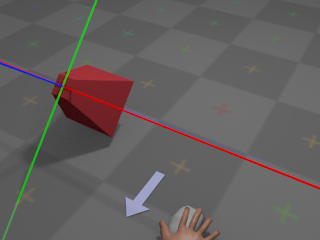
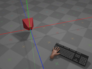
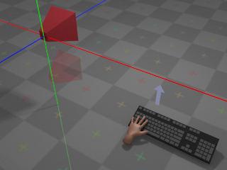
With no input from the mouse, the camera remains at its
current orientation:
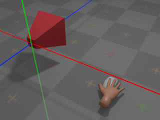
The green line denotes the camera's local Y axis, the red line denotes the
camera's local X axis, and the blue line denotes the camera's local
Z axis.
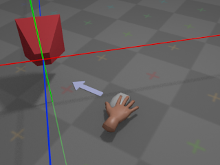
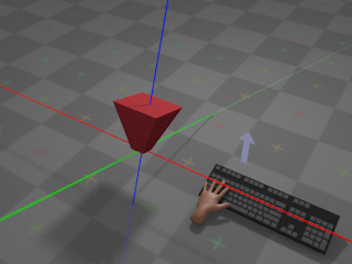
If the user moves the mouse left, the camera will rotate around the
global
Y axis and appear to turn left:
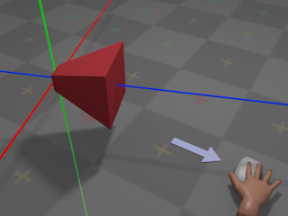
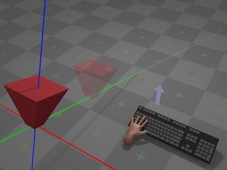
If the user moves the mouse right, the camera will rotate around the
global
Y axis and appear to turn right:
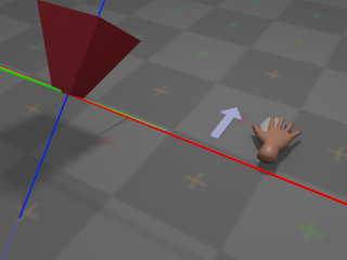
If the user pushes the mouse away,
the camera will rotate around its own local X axis and appear to turn
upwards:
If the user pulls the mouse towards,
the camera will rotate around its own local X axis and appear to turn
downwards:
The choice of whether towards and
away
mean "look down" and "look up",
or "look up" and "look down", respectively, is a matter
of personal taste. Most games and simulations provide an option to
invert the Y axis for mouse control, so that moving the mouse
away
results in the camera turning
downwards, and so on.
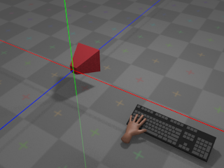
With no input from the keyboard, the camera remains at its
current position:
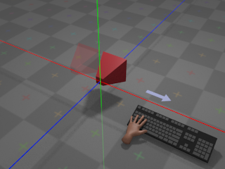
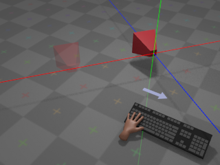
If the user presses whatever key is assigned to
right,
the camera moves towards positive infinity along its own local
X axis at a configurable rate:
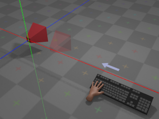
If the user presses whatever key is assigned to
left,
the camera moves towards negative infinity along its own local
X axis at a configurable rate:
Note that movement occurs along the local X
axis; if the camera has been
rotated
around
the global Y axis, then the local X axis has been transformed as a result,
and movement will occur along a different trajectory than in the unrotated
case:
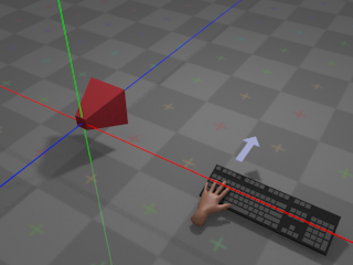
If the user presses whatever key is assigned to
forward,
the camera moves towards negative infinity along its own local
Z axis at a configurable rate:
Whether forward is considered to be towards
positive
or
negative
infinity on the Z axis is more or less a property of the coordinate system
used by the rendering system. Systems such as
OpenGL
traditionally
use a right-handed coordinate system, with
forward
pointing towards negative infinity. Systems
such as
Direct3D
traditionally use a left-handed coordinate
system, with
forward
pointing towards positive infinity. The
com.io7m.jcamera
package assumes a
right-handed
coordinate system.
As with movement on the
local X axis,
forward/backward movement occurs on the camera's local Z axis and is
therefore affected by
rotation around the Y axis.
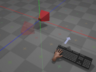
Finally, if the user presses whatever key is assigned
to up,
the camera moves towards positive infinity along its local Y axis (with
down
moving the camera towards negative infinity, accordingly):

Note that up and
down
movement occurs on the local Y axis and is therefore affected by the
current orientation
of the camera:
All other movement is restricted. The camera cannot, for example, rotate
around its own local Z axis (the roll rotation,
in aircraft terminology).
The rest of this section attempts to give a mathematical description
of a camera system that implements the above behaviour, and describes
the design and implementation of the camera system derived from the
description as it exists in the
com.io7m.jcamera
package.
Camera Mathematics
An fps-style camera can be represented
as a 3-tuple (p, h, v), where
p
is the position of the camera,
h
is an angle around the
camera's local X axis in radians, and
v
is an angle around the
global Y axis in radians. In order to implement forward/backward and
left/right movement (and to derive a final
view matrix
so that the camera
can be used to produce a viewing transform for 3D graphics), it's
necessary to derive a 3-tuple of orthonormal
direction vectors
(forward, right, up)
from the angles h and
v.
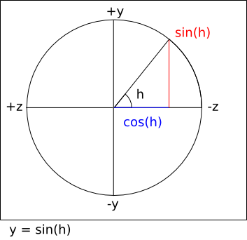
Given the standard trigonometric functions:
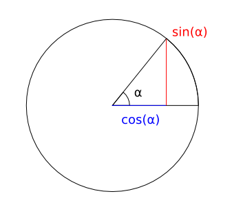
It's possible to calculate the three components of the
forward
vector by assigning
pairs of axes to the unit circle and using three equations:
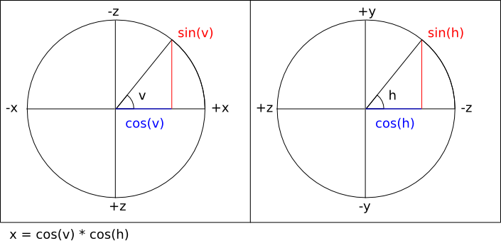
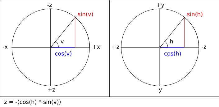
Note that the sign of the right hand side of the last equation
is inverted in order to take into account the fact that the
viewing direction is towards negative Z.
In most mathematics texts, a positive rotation around an axis
represents a counter-clockwise rotation when viewing the system along
the negative direction of the axis in question. Adhering to this
convention, the equations for calculating the
right
vector are identical
except for the fact that the equations work with a value of
v - (π / 2)
instead of
v
(a clockwise rotation
of 90°).
Finally, calculating the
up
vector is simply a matter of calculating the cross product
cross (right, forward).
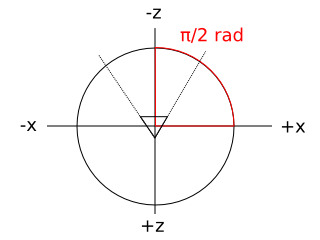
The com.io7m.jcamera package
assumes that a camera with no rotation or translation applied is
placed at the origin position
p = (0, 0, 0)
with h = 0 and
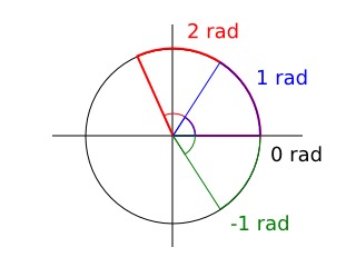
v = π / 2. The reason for the
value of v is that in most
mathematics texts, an angle of
0
radians is illustrated as pointing to the right:
In a typical OpenGL configuration, the viewer is placed at the
origin looking towards negative infinity on the Z axis, and the X
axis appears to run horizontally, perpendicular to the viewing
direction. Given this convention, it's somewhat intuitive to map
those axes to the unit circle as follows (assuming a second observer
looking down onto the scene towards negative infinity on the Y axis):
Using this convention means that the values derived from the vector
equations above can be used directly to compute a
view matrix
in the coordinate
system conventionally used by OpenGL.
As a concrete example, using the default position and orientation
given above, the resulting vectors are calculated as
[
ExampleDefaultVectors.hs]:
        module ExampleDefaultVectors where

import qualified Vector3f

h :: Float
h = 0

v :: Float
v = pi / 2.0

p :: Vector3f.T
p = Vector3f.V3 0.0 0.0 0.0

forward_x :: Float
forward_x = cos (v) * cos (h)
--        = cos (π / 2) * cos (0)
--        = 0 * 1
--        = 0

forward_y :: Float
forward_y = sin (h)
--        = sin (0)
--        = 0

forward_z :: Float
forward_z = -(cos (h) * sin (v))
--        = -(cos (0) * sin (π / 2))
--        = -(1 * 1)
--        = -1

forward :: Vector3f.T
forward = Vector3f.V3 forward_x forward_y forward_z
--      = (0, 0, -1)

right_x :: Float
right_x = cos (v - (pi / 2.0)) * cos (h)
--      = cos (0) * cos (0)
--      = 1 * 1
--      = 1

right_y :: Float
right_y = sin (h)
--      = sin (0)
--      = 0

right_z :: Float
right_z = -(cos (h) * sin (v - (pi / 2)))
--      = -(cos (0) * sin (0))
--      = -(1 * 0)
--      = 0

right :: Vector3f.T
right = Vector3f.V3 right_x right_y right_z
--    = (1, 0, 0)

up :: Vector3f.T
up = Vector3f.cross right forward
-- = ((right_y * forward_z) - (right_z * forward_y),
--    (right_z * forward_x) - (right_x * forward_z),
--    (right_x * forward_y) - (right_y * forward_x))
-- = ((0 * -1) - (0 * 0),
--    (0 * 0) - (1 * -1),
--    (1 * 0) - (0 * 0))
-- = (0, 1, 0)
The resulting forward,
right, and
up
vectors are consistent with the
Z,
X,
and Y axes typically used in
OpenGL.
With the forward and
right
vectors calculated, it is
now trivial to derive forward/backward and left/right movement. Forward
movement by d units is simply a
positive translation of the camera position
p
along the
forward
vector by d units
[
Forward.hs]:
        module Forward where

import qualified Vector3f

move_forward :: Vector3f.T -> Vector3f.T -> Float -> Vector3f.T
move_forward p forward d = Vector3f.add3 p (Vector3f.scale forward d)
A backward movement is simply the same equation with a negative
d
distance:
        module Backward where

import qualified Vector3f
import qualified Forward

move_backward :: Vector3f.T -> Vector3f.T -> Float -> Vector3f.T
move_backward p forward d = Forward.move_forward p forward (-d)
Moving right is a positive translation of the camera position
p
along the
right
vector by d units:
        module Right where

import qualified Vector3f

move_right :: Vector3f.T -> Vector3f.T -> Float -> Vector3f.T
move_right p right d = Vector3f.add3 p (Vector3f.scale right d)
Moving left is simply the same equation with a negative
d
distance:
        module Left where

import qualified Vector3f
import qualified Right

move_left :: Vector3f.T -> Vector3f.T -> Float -> Vector3f.T
move_left p right d = Right.move_right p right (-d)
Moving up is a positive translation of the camera position
p
along the
up
vector by d units:
        module Up where

import qualified Vector3f

move_up :: Vector3f.T -> Vector3f.T -> Float -> Vector3f.T
move_up p up d = Vector3f.add3 p (Vector3f.scale up d)
Moving down is simply the same equation with a negative
d
distance:
        module Down where

import qualified Vector3f
import qualified Up

move_down :: Vector3f.T -> Vector3f.T -> Float -> Vector3f.T
move_down p up d = Up.move_up p up (-d)
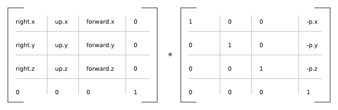
The right,
up, and
forward
vectors form an orthonormal
basis for a coordinate system. In practical terms, they provide the
rotational component for a combined rotation and translation that can
be used to transform arbitrary coordinates given in
world space
to
eye space
(also known as
view space). This is what allows the
camera system to actually be used as a camera in 3D simulations. A
matrix that rotates vectors according to the calculated camera vectors
is given by
[
ViewRotation.hs]:
        module ViewRotation where

import qualified Matrix4f
import qualified Vector3f
import qualified Vector4f
import Vector3f (x, y, z)

rotation :: (Vector3f.T, Vector3f.T, Vector3f.T) -> Matrix4f.T
rotation (right, up, forward) =
  Matrix4f.T {
    Matrix4f.column_3 = Vector4f.V4  0.0         0.0         0.0        1.0,
    Matrix4f.column_2 = Vector4f.V4 (x forward) (y forward) (z forward) 0.0,
    Matrix4f.column_1 = Vector4f.V4 (x up)      (y up)      (z up)      0.0,
    Matrix4f.column_0 = Vector4f.V4 (x right)   (y right)   (z right)   0.0
  }
A matrix that translates vectors according to the current camera
position is given by
[
ViewTranslation.hs]:
        module ViewTranslation where

import qualified Matrix4f
import qualified Vector3f
import qualified Vector4f
import Vector3f (x, y, z)

translation :: Vector3f.T -> Matrix4f.T
translation p =
  let np_x = -(x p)
      np_y = -(y p)
      np_z = -(z p)
  in
    Matrix4f.T {
      Matrix4f.column_3 = Vector4f.V4 np_x np_y np_z 1.0,
      Matrix4f.column_2 = Vector4f.V4 0.0  0.0  1.0  0.0,
      Matrix4f.column_1 = Vector4f.V4 0.0  1.0  0.0  0.0,
      Matrix4f.column_0 = Vector4f.V4 1.0  0.0  0.0  0.0
    }
        module View where

import ViewTranslation (translation)
import ViewRotation (rotation)
import qualified Matrix4f
import qualified Vector3f

view_matrix :: Vector3f.T -> (Vector3f.T, Vector3f.T, Vector3f.T) -> Matrix4f.T
view_matrix p (right, up, forward) =
  Matrix4f.mult (rotation (right, up, forward)) (translation p)
Camera Implementation
In the com.io7m.jcamera package,
the interface exposed by an fps-style camera
is described by the
JCameraFPSStyleType
type. The actual implementation of the
camera mathematics
is given in the
JCameraFPSStyle
type.
A small point to note about the implementation:
The
forward, right, and
up
vectors are calculated lazily whenever the user attempts
to perform an operation that involves them. The vectors are derived only
from the current camera
angles and so are not recomputed if the angles have not been changed since
the vectors were
last calculated.
Input
In the com.io7m.jcamera package,
an input is a simple abstraction intended
to keep
integrators
insulated from the platform-specific details of keyboard and mouse input.
With the
behaviour
described in the first subsection, there are two types of input:
Discrete
input (where the user presses
a key and the input is assumed to be constant until the key is released)
and continuous input (where the user
moves a mouse and a stream of new mouse position vectors are generated).
Discrete input can be represented by a simple boolean flag, and continuous
input can be represented by summing the received input until an
integrator is ready to receive it.
        module Input (T (..)) where

data T = T {
  is_moving_backward  :: Bool,
  is_moving_forward   :: Bool,
  is_moving_left      :: Bool,
  is_moving_right     :: Bool,
  is_moving_up        :: Bool,
  is_moving_down      :: Bool,
  rotation_horizontal :: Float,
  rotation_vertical   :: Float
} deriving (Eq, Show)
When the user presses whatever is key assigned to
up, the corresponding boolean field in
the data structure is set to true. When
the user releases the key, the corresponding field is set to
false.
The situation for mouse movement is slightly more complex. Most
OS-specific
windowing systems will provide the user with the current mouse cursor
coordinates
as a pair of integer offsets (in pixels) relative to some origin. Some
systems
have the origin (0, 0) at the
top-left corner of the
screen/window, whilst others have it at the bottom-left corner of the
window.
Additionally, the density of displays is increasing at a steady rate. A
monitor
manufactured five years ago may be 40cm wide and have a resolution that
fits
1440 pixels into that width. A modern display may be the same width but
have
over four times as many pixels in the same space. A camera system that
recklessly consumes coordinates given in pixels is going to behave
differently
on a screen that has a higher density of pixels than it would on an older,
lower
resolution display.
In order for the com.io7m.jcamera package
to remain system-independent, it's necessary to provide a way to map mouse
input
to a simple and consistent set of generic
rotation coefficients
that can be consumed by an
integrator. The rotation coefficients are a pair of values
(rx, ry)
expressing the intention to rotate
the camera, with
rx
affecting rotation around the camera's vertical axis, and
ry
affecting rotation around the camera's horizontal axis. In effect, when
rx == -1.0, the camera should appear
to
rotate
right
[2]
. When rx == 1.0,
the camera should appear to rotate left.
When
ry == 1.0, the camera should appear
to rotate
up. When ry ==
-1.0,
the camera should appear to rotate down.
The
coefficients linearly express fractional rotation, so a rotation of
0.5
is exactly half as much rotation as
1.0.
The scheme used to map screen positions to coefficients is as follows:
- When the mouse cursor is in the exact center of the screen, the resulting rotation coefficients are (0, 0).
- When the mouse cursor is in the uppermost, rightmost position of the screen q, the resulting rotation coefficients are (-1.0, 1.0).
- When the mouse cursor is in the lowermost, leftmost position of the screen p, the resulting rotation coefficients are (1.0, -1.0).
- The rotation coefficients for any other position on the screen can be derived from simple linear interpolation between p and q.
In order to actually map screen positions to rotation coefficients, it's
necessary
to take into account the windowing-system-specific origin. It's necessary
to define
a function that takes a mouse region representing
the width and height of the screen with information labelling the origin,
and a pair
of screen/window-space coordinates (sx,
sy), and
returns a pair of rotation coefficients
[
MouseRegion.hs]:
        module MouseRegion (T, newRegion, coefficients) where

data Origin =
    TopLeft
  | BottomLeft
    deriving (Eq, Show)

data T = T {
  origin   :: Origin,
  width    :: Float,
  height   :: Float,
  center_x :: Float,
  center_y :: Float
} deriving (Eq, Show)

newRegion :: Origin -> Float -> Float -> T
newRegion o w h = T {
  origin   = o,
  width    = w,
  height   = h,
  center_x = w / 2.0,
  center_y = h / 2.0
}

coefficients :: T -> (Integer, Integer) -> (Float, Float)
coefficients r (sx, sy) =
  let fx = fromIntegral sx
      fy = fromIntegral sy
      ox = ((fx - center_x r) / width r) * 2.0
      oy = ((fy - center_y r) / height r) * 2.0
  in
    case (origin r) of
      TopLeft    -> (-ox, -oy)
      BottomLeft -> (-ox, oy)
The assumption here is that the mouse cursor will be
warped
back to the center of the screen at periodic
intervals. If this did not occur, the mouse cursor would eventually reach
one or
more edges of the screen and would be unable to travel further, halting
any rotation
in those directions.
In event-based windowing systems, every
time the
user moves the mouse, a mouse event is
generated
containing the current cursor position. In some systems, the user must
explicitly
ask for the current mouse position when it is needed. In the former case,
new
rotation coefficients will be generated repeatedly. In the latter case,
the
user will typically ask for the current mouse position at the beginning of
rendering the current simulation frame, and therefore will only receive a
single
set of coefficients (effectively representing the furthest distance that
the mouse
travelled during that time period). In the
com.io7m.jcamera
package, an
integrator
will
read (and reset to (0.0, 0.0))
the current rotation coefficients from an input at a (typically) fixed
rate. The current rotation coefficients stored in an input therefore
represent the sum of mouse movements for a given elapsed time period. To
this
end, the
JCameraFPSStyleInput
type in the com.io7m.jcamera package
provides
an interface where the user simply submits new rotation coefficients each
time
they are received, and the type keeps a running total of the coefficients.
This
allows the input system to work the same way regardless of whether the
user
has to ask for mouse input, or is receiving it piecemeal via some event
system.
By taking the width and height of the screen in pixels, and dividing as
shown in the above equations, the resulting coefficients are
screen-density independent. In other words,
if the user moves the cursor halfway across the screen on a very high
density display, the resulting coefficients are the same as those
resulting
from a user moving the cursor across the same distance on a much lower
density display, even though the distances expressed in pixels are very
different.
In the com.io7m.jcamera package,
fps-style inputs are represented by the
JCameraFPSStyleInput
type, and mouse regions are represented by the
JCameraFPSStyleMouseRegion
type.
Integrators
Linear Integrators
A linear integrator updates the position
of a camera over time.
In physics, the first derivative of
position
with respect to time is
velocity. The second derivative of
position with respect to time is
acceleration.
Newton's second law of motion relates force
f
with mass m and acceleration
a
[
SecondLaw.hs]:
        module SecondLaw where

f :: Float -> Float -> Float
f m a = m * a
Rearranging the equation, acceleration is given in terms of
[
SecondLawRewrite.hs]:
        module SecondLawRewrite where

a :: Float -> Float -> Float
a f m = (1 / m) * f
However, if m is assumed to
be 1,
a = (1 / 1) * f = f. So, rather than
assign mass
to a camera and try to apply forces, it's possible to simply apply
acceleration
as a (configurable) constant term directly. Linear integrators in the
com.io7m.jcamera
package are
represented as 8-tuples
(a, c, d, i, ms, sf, sr, su)
where:
- a is the acceleration to be applied, given in units-per-second-per-second.
- c is the camera to be affected.
- d is the drag factor.
- i is an input.
- ms is the maximum speed for the camera, in units-per-second.
- sf current forward speed of the camera, in units-per-second.
- sr current right speed of the camera, in units-per-second.
- su current up speed of the camera, in units-per-second.
The meaning of units mentioned above is
application specific. An application might choose to map units to meters,
or miles, or any other arbitrary measure of distance.
As mentioned, an integrator makes changes to the position and orientation
of a camera over a given delta time period.
In most simulations, the camera will be updated at a fixed rate of
something
approaching 60 times per second. The
delta
time in this case would be given by
delta = 1.0 / 60.0 = 0.0166666....
The
integrator calculates a speed for each of the three
(right, up, forward)
axes in turn based
on the current linear acceleration/deceleration values, and the data from
the associated input, and
tells the associated camera to move based on the resulting speeds.
For the forward axis, the integrator
calculates a forward speed sfr based
on the previous forward speed sf, the
state of the input i, the
acceleration a, and the drag factor
d, and increases the camera position
by
sfr
units along the forward axis. The
forward speed is clamped to the configurable range
[-ms, ms].
Specifically, the procedure is given by
[
IntegratorForward.hs]:
        module IntegratorForward where

import qualified Clamp
import qualified Vector3f
import qualified Input

forward_speed :: Input.T -> Float -> Float -> Float -> Float
forward_speed i sf a delta =
  if (Input.is_moving_forward i)
  then sf + (a * delta)
  else sf

backward_speed :: Input.T -> Float -> Float -> Float -> Float
backward_speed i sf a delta =
  if (Input.is_moving_backward i)
  then sf - (a * delta)
  else sf

forward :: (Vector3f.T, Vector3f.T, Float, Input.T, Float, Float, Float) -> Float -> (Vector3f.T, Float)
forward (p, v_forward, sf, i, a, d, ms) delta =
  let
    sf0 = backward_speed i (forward_speed i sf a delta) a delta
    sf1 = Clamp.clamp sf0 (-ms, ms)
    pr  = Vector3f.add3 p (Vector3f.scale v_forward (sf1 * delta))
    sfr = sf1 * (d ** delta)
  in
    (pr, sfr)
The drag factor is a configurable value
that specifies how the camera will slow down over time. Ideally, when the
user is not telling the camera to move, the camera is either stationary
or on its way to becoming stationary. A drag factor
d
will result in a speed
s'
by
s' = s * (d ** delta). Intuitively,
the drag factor can be seen as the fraction of the original speed that
will remain after one second of not receiving any acceleration. If
d = 0.0, any object not having
acceleration applied will immediately stop. If
d = 1.0, an object will continue
moving indefinitely
[3]. A drag factor of 0.0 will
also imply an overall movement speed penalty due to the way integration is
performed. Usually, a drag factor of
0.0
is a bad idea - values closer to
0.0001
give the same abrupt behaviour but with slightly smoother results and less
of a movement speed penalty.
Integration for the other axes is identical, modulo the parts of the
input
that are sampled
[
IntegratorRight.hs]
and
[
IntegratorUp.hs]:
        module IntegratorRight where

import qualified Clamp
import qualified Vector3f
import qualified Input

right_speed :: Input.T -> Float -> Float -> Float -> Float
right_speed i sf a delta =
  if (Input.is_moving_right i)
  then sf + (a * delta)
  else sf

left_speed :: Input.T -> Float -> Float -> Float -> Float
left_speed i sf a delta =
  if (Input.is_moving_left i)
  then sf - (a * delta)
  else sf

right :: (Vector3f.T, Vector3f.T, Float, Input.T, Float, Float, Float) -> Float -> (Vector3f.T, Float)
right (p, v_right, sf, i, a, d, ms) delta =
  let
    sf0 = left_speed i (right_speed i sf a delta) a delta
    sf1 = Clamp.clamp sf0 (-ms, ms)
    pr  = Vector3f.add3 p (Vector3f.scale v_right (sf1 * delta))
    sfr = sf1 * (d ** delta)
  in
    (pr, sfr)
        module IntegratorUp where

import qualified Clamp
import qualified Vector3f
import qualified Input

up_speed :: Input.T -> Float -> Float -> Float -> Float
up_speed i sf a delta =
  if (Input.is_moving_up i)
  then sf + (a * delta)
  else sf

down_speed :: Input.T -> Float -> Float -> Float -> Float
down_speed i sf a delta =
  if (Input.is_moving_down i)
  then sf - (a * delta)
  else sf

up :: (Vector3f.T, Vector3f.T, Float, Input.T, Float, Float, Float) -> Float -> (Vector3f.T, Float)
up (p, v_up, sf, i, a, d, ms) delta =
  let
    sf0 = down_speed i (up_speed i sf a delta) a delta
    sf1 = Clamp.clamp sf0 (-ms, ms)
    pr  = Vector3f.add3 p (Vector3f.scale v_up (sf1 * delta))
    sfr = sf1 * (d ** delta)
  in
    (pr, sfr)
The type of linear integrators in the
com.io7m.jcamera
is
JCameraFPSStyleLinearIntegratorType,
with the default implementation being
JCameraFPSStyleLinearIntegrator.
Angular Integrators
An angular integrator updates the
orientation
of a camera over time.
Integration of orientation occurs in almost exactly the same manner as
integration of
position;
orientation is treated as a pair of scalar rotations around two axes, and
the
rotation values are increased by speed values calculated from acceleration
values for each axis. Integration of rotations around the vertical axis is
given by
[
IntegratorAngularVertical.hs]:
        module IntegratorAngularVertical where

import qualified Clamp
import qualified Input

vertical :: (Float, Float, Input.T, Float, Float, Float) -> Float -> (Float, Float)
vertical (v, sv, i, a, d, ms) delta =
  let
    sf0 = sv + ((Input.rotation_vertical i) * a * delta)
    sf1 = Clamp.clamp sf0 (-ms, ms)
    vr  = v + (sf1 * delta)
    sfr = sf1 * (d ** delta)
  in
    (vr, sfr)
Note that the acceleration around the axis is multiplied by the
rotation
coefficients
taken from the input.
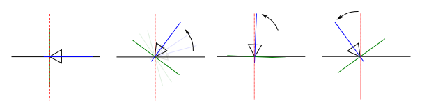
Rotation around the horizontal axis is identical, except that the actual
camera itself may clamp rotations around
the horizontal axis. The reason for this is simple: If rotations are not
clamped, and the user rotates the camera upwards or downwards, there comes
a point where the camera's rotation value wraps around and the camera
begins
to rotate in the opposite direction, as illustrated:
The practical result of the above wrapping is that the user would, for
example,
be rotating the camera up towards the ceiling, the camera would reach the
limit
of rotation, and suddenly the camera would be facing the opposite
direction
and rotating down towards the floor again. This behaviour would be
irritating,
so cameras may optionally clamp rotations
and are required to indicate when clamping occurs so that the integrator
can
zero the speed of rotation around that axis. The reason for the zeroing of
the rotation speed is that if the speed were not zeroed, and the rotation
around the axis was proceeding at, say,
100
radians per second, the user would have to cause the rotation to decrease
by over 100 radians per second in the
opposite direction in order to get the camera to rotate at all. In effect,
the camera would appear to reach the limit of rotation, stop, and then the
user would have to scrub the mouse repeatedly in the opposite direction
in order to get rotation to begin again in the opposite direction.
The type of angular integrators in the
com.io7m.jcamera
is
JCameraFPSStyleAngularIntegratorType,
with the default implementation being
JCameraFPSStyleAngularIntegrator.
Aggregate Integrators
Usually, a user will want cameras to both move and rotate, as
opposed to just one or the other. The
com.io7m.jcamera
package
provides the
JCameraFPSStyleIntegratorType
which aggregates both the
linear
and
angular
integrators, with the default implementation given by
JCameraFPSStyleIntegrator.
[2]
While it may be more intuitive to think of the rightmost position being
1.0
and the leftmost position being
-1.0, recall that a positive
rotation
represents a counter-clockwise rotation around an axis when looking
towards
negative infinity on that axis. For a first-person camera system, a
negative
rotation on the vertical axis therefore represents a turn to the
right.
[3]
This is obviously the correct physical behaviour for an object that
is not being influenced by any forces, but it's not very useful
behaviour
for a camera system!