com.io7m.jcamera
0.6.0
Spherical Camera
- 3.3.1. Overview
- 3.3.2. Camera Behaviour
- 3.3.3. Camera Mathematics
- 3.3.4. Camera Implementation
- 3.3.5. Input
- 3.3.6. Integrators
- 3.3.7. Linear Integrators
- 3.3.8. Angular Integrators
- 3.3.9. Aggregate Integrators
Overview
Most real-time strategy games implement some variation of a
so-called spherical camera (also
sometimes known as an orbital camera).
A spherical camera always points towards, and stays a given distance
from, a target point.
One of the classic examples of this type of camera was implemented
in Bungie's
Myth II: Soulblighter.
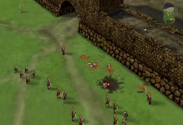
The camera described here implements a useful subset of the
capabilities of Myth II's camera
system
[4]
.
A restricted form of this camera is present in Blizzard's
Starcraft II.
The mouse-control scheme for
Starcraft's
camera is generally considered to be the definitive one amongst
real-time strategy games, and the camera described here shamelessly
duplicates it.
It is recommended that the reader fully understand the implementation
and mathematics of
fps-style cameras
as most of the implementation described here uses the same approach
and concepts.
Camera Behaviour
A spherical camera remains at a given radius
from
a movable target point. The orientation of
the
camera is derived from a heading angle and
an
incline
angle.
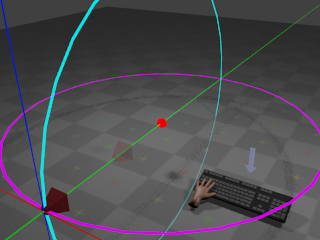
With no input from the mouse, the camera remains at its
current orientation:
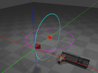
The red sphere indicates the target point.
The camera remains at a given radius from
the target point, with the cyan ring indicating the path that the camera
would take if the incline were to change,
and the magenta ring indicating the path that the camera would take if
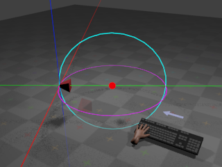
the heading were to change. If the user
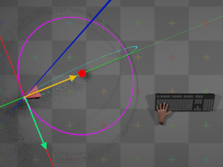
presses the whatever key is assigned to orbit
left,
the camera heading angle begins to
decrease
at a configurable rate.
This results in the camera rotating horizontally around the target point:
If the user presses whatever key is assigned to
orbit right,
the camera begins to rotate around the same arc but in the opposite
direction.
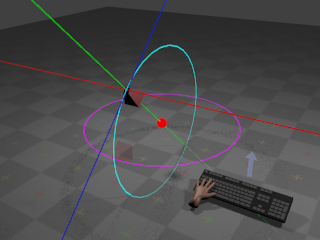
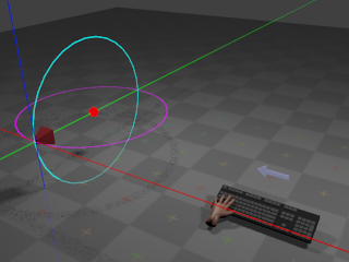
If the user presses whatever key is assigned to
orbit up,
the camera incline angle begins to
increase
at a configurable rate. This results in
the camera rotating vertically around the target point:
If the user presses whatever key is assigned to
orbit down,
the camera begins to rotate around the same arc but in the opposite
direction.
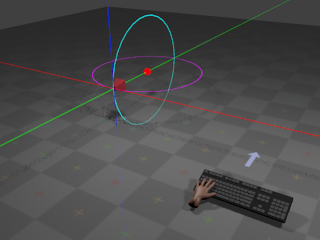
If the user presses whatever key is assigned to zoom
out,
the radius begins to increase at a
configurable
rate. This results in the camera giving the effect of
zooming out:
If the user presses whatever key is assigned to zoom
in,
the radius begins to decrease at a
configurable
rate. This results in the camera giving the effect of
zooming in.
The target point can also move according to
user input:
Whether target point movement occurs due to keyboard or mouse input is
a matter of taste. The implementation described here provides both.
Movement
of the target point occurs along directions derived from the camera's
current
orientation. When the user instructs the target point to move
up, the point begins to move towards
positive infinity on the global Y axis. When the user instructs the target
point to move forward, the target point
begins
to move along the direction defined by projecting the camera's current
forward
vector onto the horizontal plane.
When the user instructs the target
point to move right, the target point
begins
to move along the direction defined by projecting the camera's current
right
vector onto the horizontal plane.
The precise definitions of these vectors are given in the following
section
on the mathematics of the camera.
Moving the target point via keyboard input works in a familiar and
unsurprising manner: When the user presses whatever key is assigned
to a particular direction, the camera moves in that direction until
the user releases the key.
Moving the target point via mouse input is more complicated, however.
Mouse movement is provided by both
dragging
and edge scrolling. When the user
drags
the mouse in a given direction,
the camera appears to move in the opposite direction by an amount
proportional to the drag distance. When the user moves the mouse
cursor to the edge of the screen,
the camera appears to move in at a constant rate in a direction
relative to the edge of the screen, until the user moves the mouse
cursor away from that edge. These descriptions are somewhat vague,
and a more formal description is given in the section on
camera mathematics.
Camera Mathematics
A spherical camera can be represented
as a 4-tuple (t, h, i, r), where
t
is the position of the target point,
h
is an angle around the
global Y axis (the heading),
i
is an angle around the
local X axis in radians (the incline),
and r is the camera's distance
from the target point (the radius). Astute
readers will notice that the defined angles are coordinates in a
spherical coordinate system,
and therefore the movement of the camera around the target point
always describes a sphere of radius r.
As with
fps-style
cameras, in order to implement forward/backward and
left/right movement (and to derive a final
view matrix
so that the camera
can be used to produce a viewing transform for 3D graphics), it's
necessary to derive a 3-tuple of orthonormal
direction vectors
(forward, right, up)
from the camera's angles and radius.
In order to derive the vectors, it's necessary to first work out
the orientation of the camera. In order to calculate a full viewing
transform, it's also necessary to calculate the actual world-space
position p of the camera.
As stated in the description of the
camera behaviour,
the camera is always oriented towards
t.
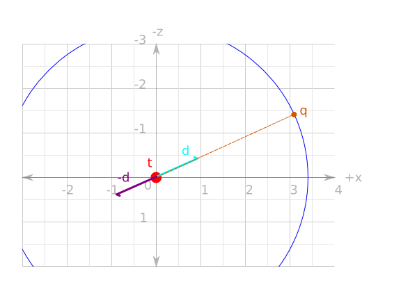
The mathematics of determining the camera's world-space position and
orientation can
be simplified if t is considered as
the origin of a new local coordinate system that will be referred to as
target-space. Transforming a world-space
position w to
target-space simply requires subtracting
t
from w. Transforming a target-space
position u to world-space requires
adding t to
u. The following diagram illustrates
all of the above, flattened onto the X/Z (horizontal) plane for ease of
viewing:
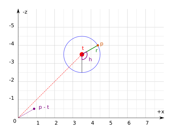
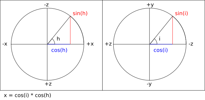
Firstly, then, to calculate the target-space camera position
q
the same equations are
used as were used when calculating the
direction vectors
for the fps-style camera. Firstly, a direction vector
d
is calculated
that points towards q from the
origin:
Then, q is simply
d
scaled by
r:
q = Vector3f.scale d r
The world-space camera position
p
is simply q added to
t:
p = Vector3f.add3 q t
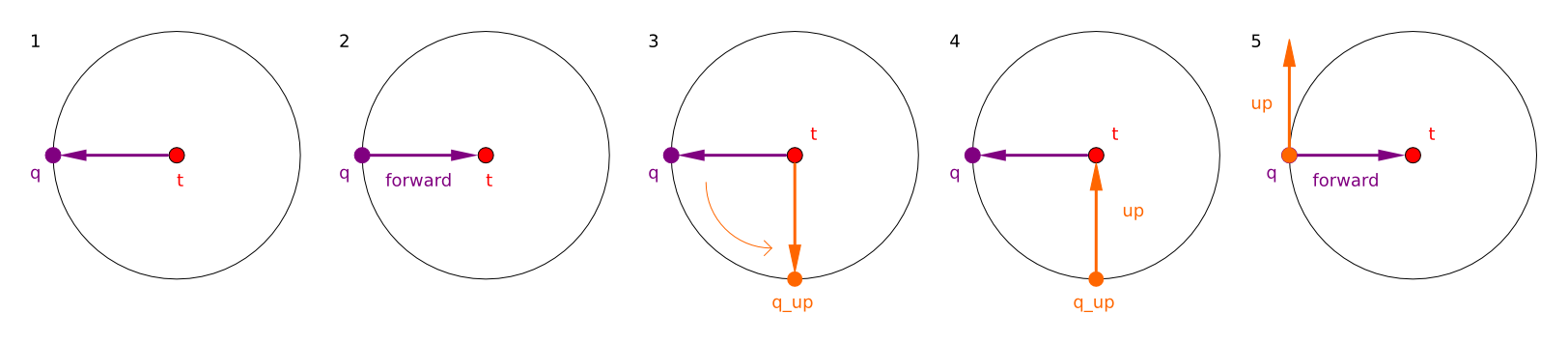
As stated, the aim is to construct a
forward
vector that points
towards t from
p. This is simply
the negation of d:
forward = Vector3f.normalize (Vector3f.scale d -1)
Constructing the
up
vector for the
camera is achieved by performing the exact same calculation
as for the forward vector
but with i - (π / 2).
Intuitively, this works by calculating
q
as if it had been orbited
downwards around the sphere, and then taking the negation
of the resulting direction vector as normal:
Finally, calculating the right vector is
simply the cross product of the forward and
up
vectors.
right = Vector3f.cross forward up
As stated earlier, forward/backward and left/right movement
occurs only on the horizontal plane. Because the camera is
not allowed to roll, the calculated
right
vector is always parallel
to the horizontal plane and can therefore be used directly. Because
the camera inclination is variable, however, the calculated
forward
vector is only parallel
to the horizontal plane when i = 0.
It's therefore necessary to calculate a
forward_on_xz
vector that is always
parallel to the horizontal plane. This is achieved by projecting
the forward vector onto the X/Z
plane via a simple orthographic projection:
project :: Vector3f.T -> Vector3f.T
project v =
  let vx = Vector3f.x v
      vz = Vector3f.z v
  in Vector3f.normalize (Vector3f.V3 vx 0.0 vz)

forward_on_xz :: Vector3f.T
forward_on_xz = project forward
There is an issue here: The projection of the forward vector resulting
from an incline of exactly
(π / 2)
or (-π / 2) radians results in a
forward
vector equal to
(0, ±1, 0), the projection of which
is the zero vector (0, 0, 0). This
means that when the camera is looking directly up towards (or directly
down upon)
the target position, the camera cannot be moved forwards or backwards.
In practice, it is rare that the incline will be exactly either these
values. The problem can be worked around entirely by clamping the possible
incline ranges to [(π / 2) + e, (-π / 2) -
e],
where e is an arbitrary very small
value.
A complete listing of all the equations given so far, using
the default inclination and heading angles, and the default
camera position is as follows
[
ExampleSphericalDefaultVectors.hs]:
module ExampleSphericalDefaultVectors where
import qualified Vector3f
heading :: Float
heading = -pi / 2.0
incline :: Float
incline = 0
radius :: Float
radius = 8
target :: Vector3f.T
target = Vector3f.V3 0 1 4
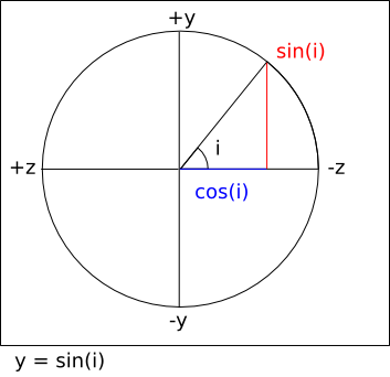
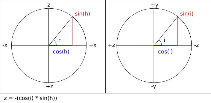
direction :: Float -> Float -> Vector3f.T
direction heading incline =
let
x = (cos heading) * (cos incline)
y = sin incline
z = -((cos incline) * (sin heading))
in
Vector3f.V3 x y z
d :: Vector3f.T
d = direction heading incline
q :: Vector3f.T
q = Vector3f.scale d radius
p :: Vector3f.T
p = Vector3f.add3 q target
forward :: Vector3f.T
forward = Vector3f.normalize (Vector3f.scale d (-1.0))
up :: Vector3f.T
up =
let d = direction heading (incline - (pi / 2.0)) in
Vector3f.normalize (Vector3f.scale d (-1.0))
right :: Vector3f.T
right = Vector3f.cross forward up
project :: Vector3f.T -> Vector3f.T
project v =
let vx = Vector3f.x v
vz = Vector3f.z v
in Vector3f.normalize (Vector3f.V3 vx 0.0 vz)
forward_on_xz :: Vector3f.T
forward_on_xz = project forward
Movement of the target point is achieved identically to the
way
fps-style cameras
move, except that the
forward_on_xz
vector is used instead of the ordinary
forward
vector for forward/backward
movement, and the global Y axis is used for
up/down movement instead of the camera's
up
vector.
View matrix
calculating is also identical, using the calculated
forward,
right,
and up vectors, and
p
for the translational components.
In order to implement
mouse control
over movement of the target point, it's necessary to somehow map
two-dimensional mouse cursor movements to three-dimensional camera
movements. All windowing systems tend to use system-specific
conventions: Some windowing systems place
(0, 0)
at the top-left corner of the
window, and others place (0, 0) at
the bottom-left corner. In order to get
system-independent
and display-density-independent mouse
control,
the com.io7m.jcamera package
borrows
a concept from OpenGL:
normalized device coordinates
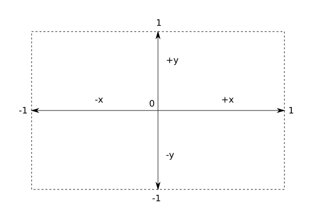
(albeit in a two-dimensional form). In normalized
device space,
the origin (0, 0) is in the center of
the screen.
The rightmost edge of the screen is x =
1, the
leftmost edge of the screen is x = -1,
the topmost
edge is y = 1, and the bottommost ege
is
y = -1:
The translation to normalized device coordinates from screen coordinates
is simple, although slightly different equations are needed for systems
that use a top-left origin as opposed to a bottom-left origin
[
NormalizedDevice.hs]:
        module NormalizedDevice where

import qualified Vector3f

width :: Float
width = 640.0

height :: Float
height = 480.0

to_ndc_from_top_left :: (Integer, Integer) -> (Float, Float)
to_ndc_from_top_left (sx, sy) =
  let
    center_x = width / 2.0
    center_y = height / 2.0
    rx = ((fromIntegral sx - center_x) / width) * 2.0
    ry = ((fromIntegral sy - center_y) / height) * 2.0
  in
    (rx, ry)

to_ndc_from_bottom_left :: (Integer, Integer) -> (Float, Float)
to_ndc_from_bottom_left (sx, sy) =
  let
    center_x = width / 2.0
    center_y = height / 2.0
    rx = ((fromIntegral sx - center_x) / width) * 2.0
    ry = ((fromIntegral sy - center_y) / height) * 2.0
  in
    (rx, -ry)
Given an arbitrary cursor position expressed as normalized device
coordinates, it's then possible to determine if the cursor is at
one or more of the screen edges. This is how
edge scrolling
is implemented.
For example, if the cursor is at (1,
1),
then it means the cursor is at the extreme top-right corner of the screen.
The simple fact that a given cursor either is or isn't at a particular
edge
can be used as a discrete input. For the spherical camera described here,
if the
cursor is moved to the top edge of the screen, it is as if the user had
pressed whatever key is assigned to forward.
The camera continues moving in that direction until the cursor is moved
away from the edge. If the cursor is moved to the right edge of the
screen, it is as if the user had pressed whatever key is assigned to
right. If the cursor is at one of the
corners, it is as if the user had pressed whatever keys are assigned
to the two relevant edges.
For the other form of mouse control - dragging
-
the same system is used to map screen-space mouse coordinates to
normalized device coordinates. However, the coordinates of the mouse
are only taken into account when the relevant mouse button is being
held
[5]
. The offsets from the center of the screen are accumulated
in the same manner as with the
rotation
coefficients
for fps-style cameras, and are reset to
(0, 0)
periodically in the same manner. Additionally, the offsets are negated
when the actual camera movement is applied. For example, if the user
has dragged the mouse to the right,
the camera is actually moved left. An
intuitive way to think of this is to imagine that the objects that the
camera is observing are on a sheet, and in order to look at a specific
object that is laying to the right of the camera, the sheet must be
pulled left to move the object into view. This is not actually mandated
by the implementation in the
com.io7m.jcamera
package;
the programmer is free to pass the non-negated offsets to the camera
in order to move it
[6]. An illustration of this (with the red frame indicating
the camera's view):
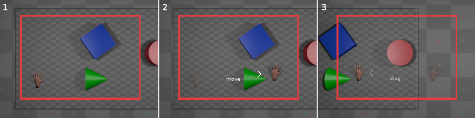
In practical terms, with the default settings, if the user drags the
mouse downward, the camera moves as if
the user had pressed whatever key is assigned to
forward
for the
duration of the drag. If the user drags the mouse
right, the camera moves as if the user
had pressed left for the duration of
the drag. The camera will correctly move diagonally if the user drags
downward
and
right.
Camera Implementation
In the com.io7m.jcamera package,
the interface exposed by a spherical camera
is described by the
JCameraSphericalType
type. The actual implementation of the
camera mathematics
is given in the
JCameraSpherical
type.
A small point to note about the implementation:
The
forward, right, and
up
vectors are calculated lazily whenever the user attempts
to perform an operation that involves them. The vectors are derived only
from the current camera
angles and so are not recomputed if the angles have not been changed since
the vectors were
last calculated.
Input
In the com.io7m.jcamera package,
an input is a simple abstraction intended
to keep
integrators
insulated from the platform-specific details of keyboard and mouse input.
As described in the section on
fps-style camera input,
input can categorized as discrete or
continuous. The details of input for
spherical cameras are slightly more complicated than for fps-style
cameras due to the more complex
control
scheme.
An input for a spherical camera in the
com.io7m.jcamera
package is
represented by the following data structure
[
InputSpherical.hs]:
        module InputSpherical (T (..)) where

data T = T {

  is_moving_backward_key    :: Bool,
  is_moving_backward_cursor :: Bool,

  is_moving_forward_key    :: Bool,
  is_moving_forward_cursor :: Bool,

  is_moving_left_key     :: Bool,
  is_moving_left_cursor  :: Bool,

  is_moving_right_key    :: Bool,
  is_moving_right_cursor :: Bool,

  is_moving_up        :: Bool,
  is_moving_down      :: Bool,

  moving_forward_continuous :: Float,
  moving_right_continuous   :: Float,

  is_orbiting_heading_positive :: Bool,
  is_orbiting_heading_negative :: Bool,
  is_orbiting_incline_positive :: Bool,
  is_orbiting_incline_negative :: Bool,

  is_zooming_in  :: Bool,
  is_zooming_out :: Bool

} deriving (Eq, Show)
In a similar manner to the fps-style
camera input,
pressing a key on the keyboard sets the corresponding boolean field
in the input to true, setting
it to false when the key is released.
In order to account for the fact that some movements can be prompted by
both the keyboard and mouse, there are separate fields for keyboard and
cursor control. For example, moving a mouse to the right edge of the
screen
sets the is_moving_right_cursor field
to true. The
moving_forward_continuous
and
moving_right_continuous
fields
represent the accumulated
dragging
for the current time period.
In the com.io7m.jcamera package,
spherical camera inputs are represented by the
JCameraSphericalInput
type, and mouse regions are represented by the
JCameraSphericalMouseRegion
type.
Integrators
Linear Integrators
A linear integrator updates the position
of a camera over time.
Linear integration of the camera is achieved in an almost identical
manner to linear integration of
fps-style
cameras,
with the addition of the changes of position caused by the continuous
input from mouse
dragging.
Changes in radius (zooming) are also handled by the linear integrator.
Calculation of the forward velocity
is given by the following equations
[
IntegratorSphericalForward.hs]:
        module IntegratorSphericalForward where

import qualified Clamp
import qualified Vector3f
import qualified InputSpherical

forward_speed :: InputSpherical.T -> Float -> Float -> Float -> Float
forward_speed i sf a delta =
  if (InputSpherical.is_moving_forward_key i || InputSpherical.is_moving_forward_cursor i)
  then sf + (a * delta)
  else sf

backward_speed :: InputSpherical.T -> Float -> Float -> Float -> Float
backward_speed i sf a delta =
  if (InputSpherical.is_moving_backward_key i || InputSpherical.is_moving_backward_cursor i)
  then sf - (a * delta)
  else sf

drag_forward_speed :: InputSpherical.T -> Float -> Float -> Float
drag_forward_speed i a delta =
  (InputSpherical.moving_forward_continuous i) * a * delta

forward :: (Vector3f.T, Vector3f.T, Float, InputSpherical.T, Float, Float, Float) -> Float -> (Vector3f.T, Float)
forward (p, v_forward_on_xz, sf, i, a, d, ms) delta =
  let
    sf0 = backward_speed i (forward_speed i sf a delta) a delta
    sf1 = Clamp.clamp sf0 (-ms, ms)
    sd  = drag_forward_speed i a delta
    sf2 = sf1 + sd
    pr  = Vector3f.add3 p (Vector3f.scale v_forward_on_xz (sf2 * delta))
    sfr = sf1 * (d ** delta)
  in
    (pr, sfr)
The first thing to note is the
drag_forward_speed
function: This calculates how much the camera should be moving in the
forward
direction based on the current accumulated continuous input. The forward
speed
calculated by the function is added to the current total speed
after
the total has been
clamped
to the speed limits. The reason for this
is simply that the speed limits are usually set reasonably low in order to
avoid
the camera getting up to too high a speed when controlled by the keyboard,
but
the low speed limits also tend to mean that the user cannot drag the mouse
fast enough
to get a comfortable movement rate. Exceeding the speed limit temporarily
is mildly
distasteful, but relies on the fact that the user is physically limited by
their own
ability to fling a piece of plastic across a desktop, and so the speed of
the camera
should not become excessively high. An alternate solution would be to have
two sets
of speed limits, one for keyboard control and another for dragging. This
is trivial
to implement, but is not implemented here for the sake of keeping the
implementation
as easy to understand as possible.
There is also a limitation in the described integrator: The camera feels
increasingly
sluggish as the camera zooms out. This is purely a perceptual issue: If
the camera
is a very long way away from an object, then the camera has to move much
further
for there to be a perceived movement onscreen than it would have to move
if it
were very close to the object. Essentially, it's desirable for the camera
to move
faster the further away it is from the target point. The way this is
achieved in the
com.io7m.jcamera
package is to associate a
pair of functions scale_linear and
scale_dragging
with the integrator that are responsible
for producing scaling factors when given the current
radius
(zoom). The linear speed, acceleration, and maximum speeds are scaled by
scale_linear, and the extra speed
produced by
dragging
is scaled by
scale_dragging
[
IntegratorSphericalForwardZoomScaled.hs]:
        module IntegratorSphericalForwardZoomScaled where

import qualified Clamp
import qualified Vector3f
import qualified InputSpherical

type ScaleFunction = Float -> Float

forward_speed :: InputSpherical.T -> Float -> Float -> Float -> Float -> ScaleFunction -> Float
forward_speed i sf a zoom scale delta =
  let accel = (scale zoom) * (a * delta) in
    if (InputSpherical.is_moving_forward_key i || InputSpherical.is_moving_forward_cursor i)
    then sf + accel
    else sf

backward_speed :: InputSpherical.T -> Float -> Float -> Float -> Float -> ScaleFunction -> Float
backward_speed i sf a zoom scale delta =
  let accel = (scale zoom) * (a * delta) in
    if (InputSpherical.is_moving_backward_key i || InputSpherical.is_moving_backward_cursor i)
    then sf - accel
    else sf

drag_forward_speed :: InputSpherical.T -> Float -> Float -> ScaleFunction -> Float
drag_forward_speed i a zoom scale delta =
  (InputSpherical.moving_forward_continuous i) * a * (scale zoom) * delta

forward :: (Vector3f.T, Vector3f.T, Float, InputSpherical.T, Float, Float, Float, Float, (ScaleFunction, ScaleFunction)) -> Float -> (Vector3f.T, Float)
forward (p, v_forward_on_xz, sf, i, a, d, ms, zoom, (scale_linear, scale_dragging)) delta =
  let
    sf0 = backward_speed i (forward_speed i sf a delta) a delta
    sms = (scale_linear zoom) * ms
    sf1 = Clamp.clamp sf0 (-sms, sms)

    sd  = drag_forward_speed i a zoom scale_dragging delta
    sf2 = sf1 + sd

    pr  = Vector3f.add3 p (Vector3f.scale v_forward_on_xz (sf2 * delta))
    sfr = sf1 * (d ** delta)
  in
    (pr, sfr)
Experimentation has shown that using the same function for
scale_dragging
and scale_linear tends to give results
that are
good for one and not the other. The default choice for
scale_dragging
is simply the
identity function, and the default choice
for scale_linear is the square root
function. This effectively scales dragging directly by the current
zoom level, and scales linear movement (caused by edge scrolling and the
keyboard)
by the square root of the current zoom level. The same scaling is applied
equally to forward and rightward movement.
Angular Integrators
An angular integrator updates the
orientation
of a camera over time.
Integration of orientation occurs in almost exactly the same manner as
integration of
position;
orientation is treated as a pair of scalar rotations around two axes, and
the
rotation values are increased by speed values calculated from acceleration
values for each axis.
Rotation by the incline angle is identical, except that the actual
camera itself may optionally clamp the
incline angle to work around the documented
projection
issue.
The type of angular integrators in the
com.io7m.jcamera
is
JCameraSphericalAngularIntegratorType,
with the default implementation being
JCameraSphericalAngularIntegrator.
Aggregate Integrators
Usually, a user will want cameras to both move and rotate, as
opposed to just one or the other. The
com.io7m.jcamera
package
provides the
JCameraSphericalIntegratorType
which aggregates both the
linear
and
angular
integrators, with the default implementation given by
JCameraSphericalIntegrator.
[4]
Myth II
allowed the target
point to orbit around the camera, as opposed to only allowing
the camera to orbit around the target point. This capability
is not widely useful and complicates the implementation of
the camera significantly, and so is omitted here.
[5]
Starcraft II uses the middle mouse button for dragging. The
com.io7m.jcamera
package
leaves it to the programmer to decide.
[6]
The "inverted" behaviour is the default camera behaviour in
Starcraft II, and is therefore used here as the default.